3.1. Setting up Your H9000
Note
Please refer to Section 4: Emote for instructions on setting up your H9000R.
Press the Setup button to enter the setup menu for the H9000. The left-hand side of the display shows a list of areas you can customize.
Use the cursor buttons or wheel to navigate to the setup screen you wish to adjust. The setup category will highlight and the right-hand side of the display will show the specific items that can be adjusted in that section.
3.1.1. Info
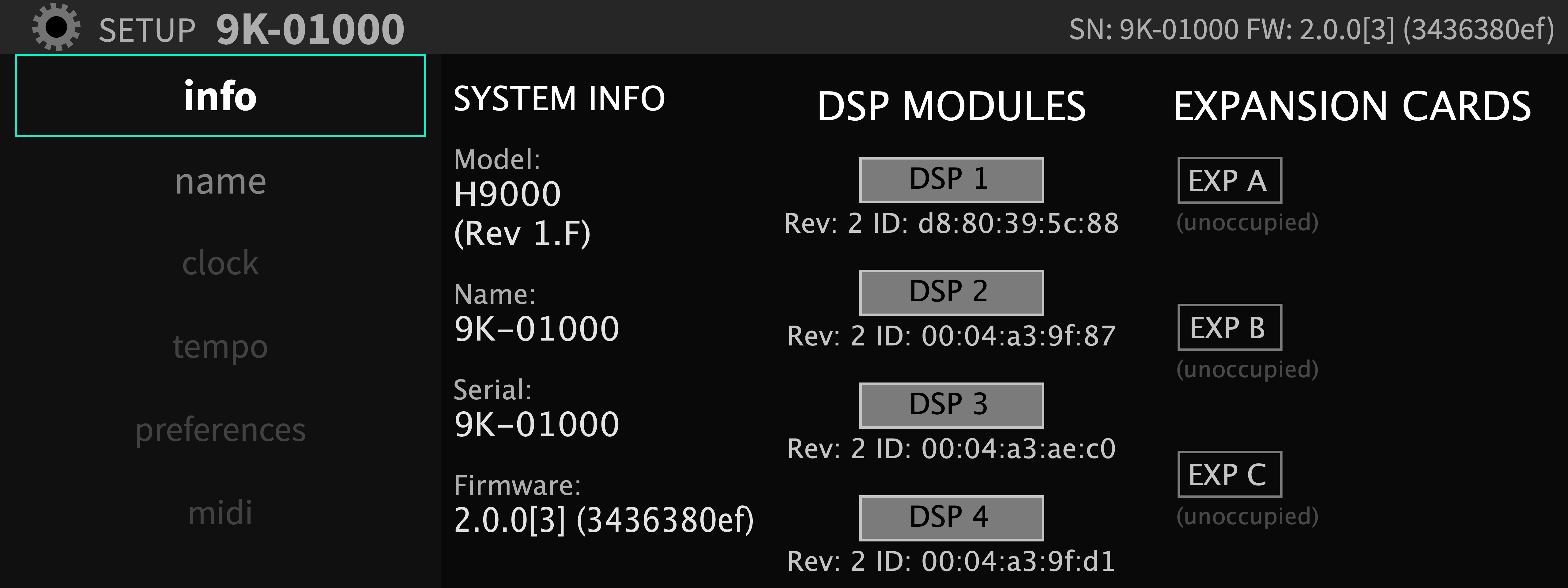
The Info screen is a display only; none of its settings can be adjusted. It provides a high-level overview of your H9000 unit, with the following information:
- System Info
Model: (In this case the H9000)
Name: The custom name that you have assigned to your unit
Serial Number
Firmware Version
- DSP Modules
This column displays revision and ID information for the individual hardware DSP modules installed in your unit. If a DSP module is displayed as (unoccupied) or OFFLINE, please refer to Section A.5: USB Self-Test Mode.
- Expansion cards
This column displays information on any expansion card(s) that are installed in the H9000’s three expansion slots (which are labeled slots A, B, and C).
3.1.2. Expansion Card Setup
This menu page displays any installed expansion cards and any relevant information pertaining to installed expansion cards (i.e. expansion card firmware version).
3.1.3. Name
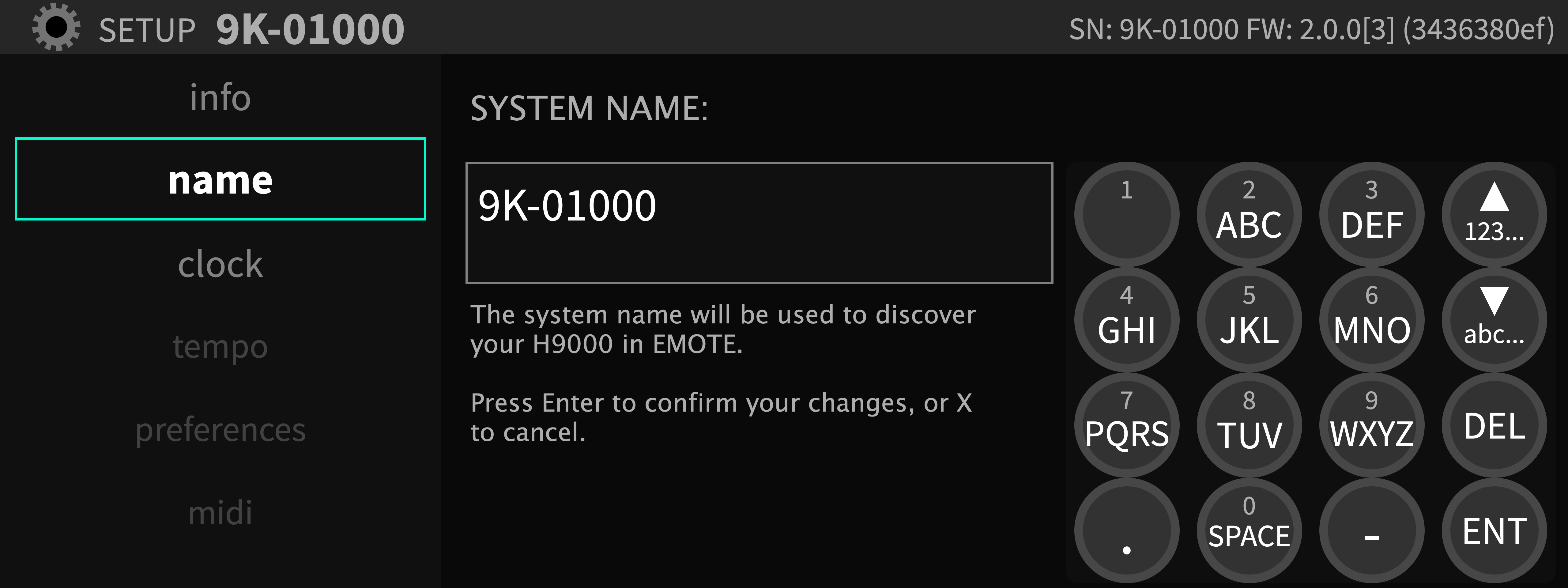
The Name screen allows you to create a custom name for your H9000. With custom names assigned, you can select the desired unit when using multiple units and controlling them with Emote.
To assign a custom name to your unit:
Use the cursor keys to navigate to the System Name field.
A “virtual number pad” is displayed, showing you which letters are available on each physical number key.
Press the front panel number keys to enter the letters of the custom name you wish to give your unit.
Press the number key repeatedly to cycle through each of the three letters.
Press the arrow down key to toggle between uppercase and lowercase letters.
Press the arrow up key to toggle between letters and special symbols.
Press the Enter key to save the custom name. You will be asked to confirm your new custom name.
Press the OK soft key to save the name, or Cancel to cancel the operation.
3.1.4. Clock
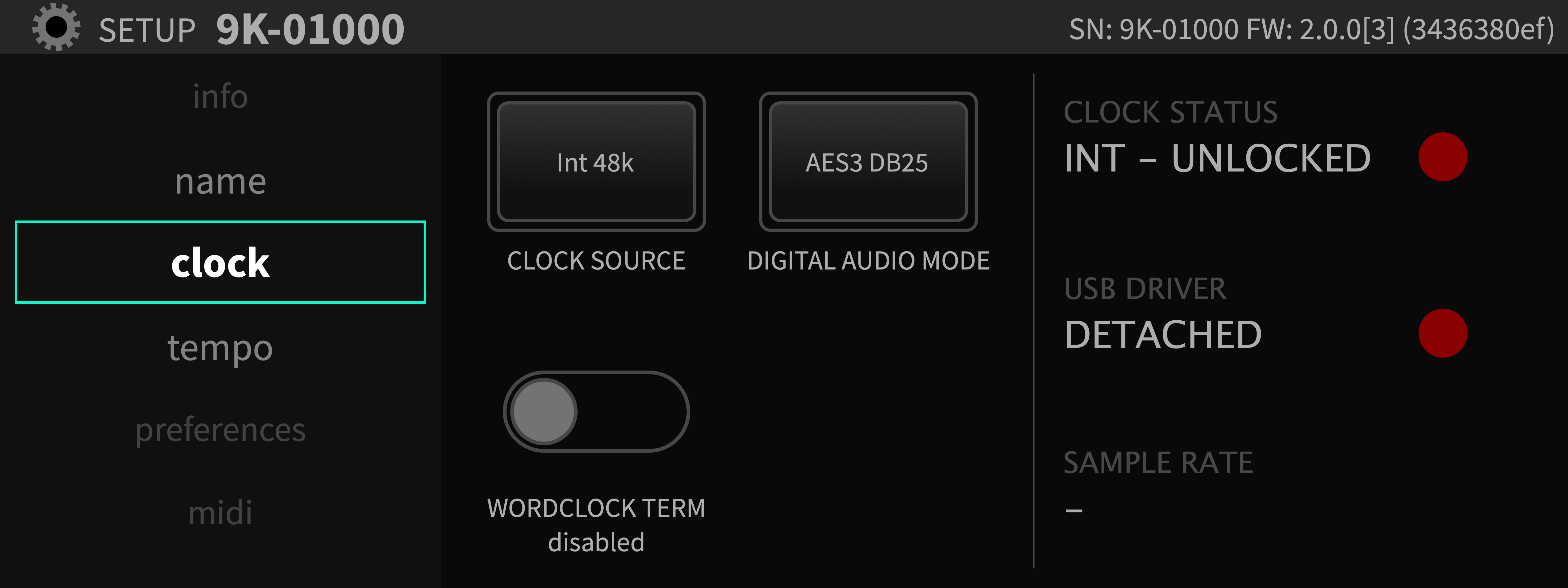
The Clock menu is where you will set the unit’s sample rate and digital audio mode.
- Clock Source
The clock source is the digital audio clock to which your H9000 synchronizes. You can select an internal clock at one of the sample rates listed below:
44.1 kHz
48 kHz
88.2 kHz
96 kHz
Alternatively, you can synchronize your H9000’s system clock to an external clock signal derived from additional sources:
AES Any (any AES signal feeding the DB-25 connector)
S/PDIF/XLR/AES in 1 (Dig 1-2)
AES In 2 (Dig 3-4)
AES In 3 (Dig 5/6)
AES in 4 (Dig 7/8)
ADAT
Word Clock
Expansion A/B/C
To adjust the clock source:
Use the cursor keys to highlight the clock source setting.
Press the Enter button or adjust the wheel to reveal up a popup menu with available choices for that setting.
Use the cursor up/down buttons or wheel to select your desired choice.
Press the enter key again to select that choice.
- Digital Audio Mode
The H9000 contains several different digital audio connectors. They are “shared” as an input source to the H9000; you choose which one you wish to make active. The Digital Audio Mode menu is where this selection is made. Use the Digital Audio mode selector to pick your preferred connector, which will then be available in the audio routing menus of the H9000. Available choices include:
AES 3 (DB-25 Connector)
AES 3 (XLR Connector)
S/PDIF (RCA Connector)
S/PDIF (Optical Connector)
ADAT (Optical Connector)
By contrast, for the outputs, the same signal is “multed” to all of the digital audio output connectors simultaneously.
- Clock Status
The right-hand side of the screen displays the status of various clocks, as follows:
Clock Status: The large virtual LED illuminates GREEN when the H9000 is locked to either its internal clock, or a valid external clock that you have selected for it to sync to. The LED illuminates RED if the H9000 is not locked. For example, if you have selected an external clock source that hasn’t been connected.
USB Driver: The large virtual LED illuminates GREEN when the H9000 has a valid USB connection to an attached computer and will display “attached.” The LED illuminates RED if the H9000 has no valid USB connection and will display “detached.”
Sample Rate: This field displays the actual sample rate at which H9000 is operating.
Note
The H9000 does not support sample rate conversion. If you want to feed the H9000 a digital audio signal, the external digital signal and the H9000 must both be locked to the same digital clock, at the same sample rate.
- Word Clock Termination Status
Sets the internal word clock termination to be enabled or disabled.
Set this to “enabled” if the H9000 is at the end of a word clock chain.
Set this to “disabled” if the H9000 is in the middle of a word clock chain and a BNC T is being used.
Warning
Use a 75 ohm BNC cable. 50 ohm BNC cables may cause clocking issues.
3.1.5. Tempo
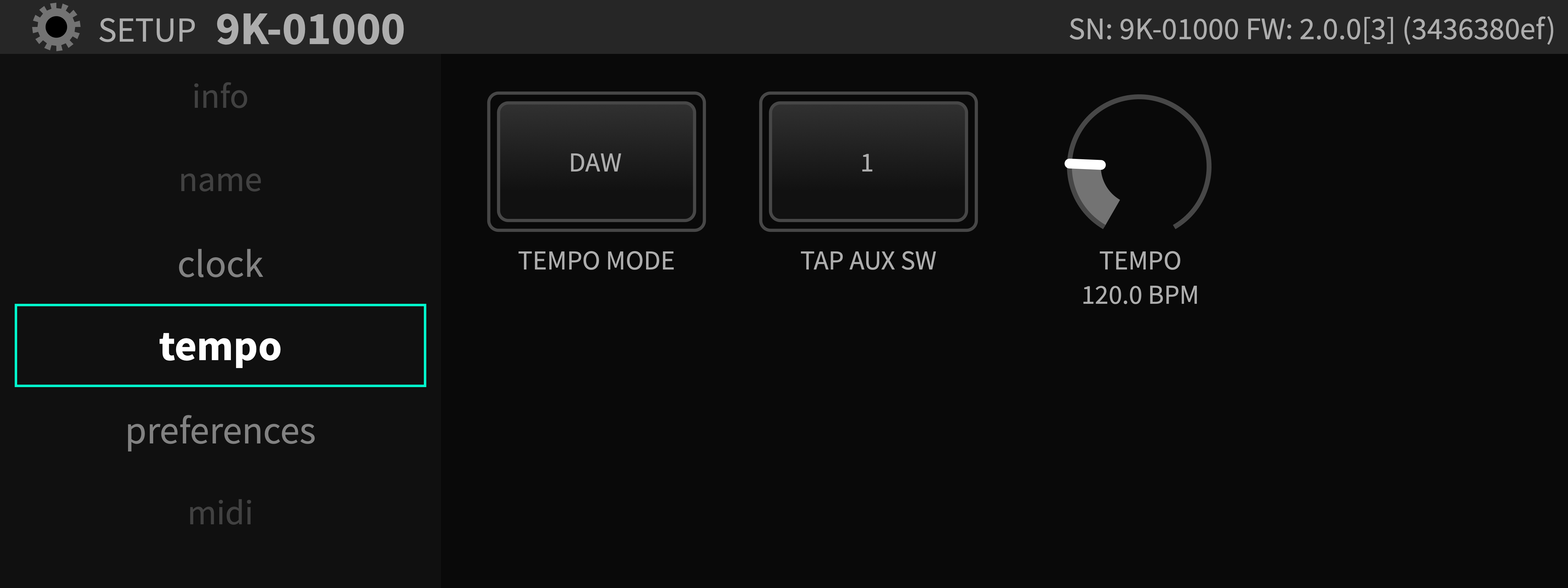
The Tempo menu provides controls for setting the H9000’s tempo.
The unit’s tempo affects the H9000’s many time-based effects, which can be synchronized to various clock sources. For example, a delay algorithm’s repeats can be synchronized to an incoming MIDI clock or your DAW. Tempo mode menu includes the following four settings:
- Off
In this mode, no MIDI clock data is received from the USB or DIN inputs. Any time-based effects will not be synchronized to a MIDI clock signal.
- Internal
In this mode, you set your own tempo, expressed as Beats per Minute (BPM). This BPM value is the tempo base for any relevant time-based effects. You can set the internal tempo in three different ways:
Tap Tempo: Tap the front panel Tap button at least two times; the H9000 will automatically set the unit’s internal tempo to the average of the most recent taps, and temporarily display the tempo in BPM on the display.
TAP AUX SW: Highlight “TAP AUX SW” and press the Enter key to assign an aux switch to Tempo.
Manual Tempo Dial: Highlight the Tempo setting, then adjust the wheel to manually select the BPM value you wish to set your tempo to.
- MIDI Clock
In this mode, the H9000 will automatically set the tempo to an incoming MIDI signal (as long as that MIDI signal contains a valid MIDI clock signal). The external MIDI clock signal can arrive either via DIN, or USB-B.
- DAW
In this mode, the H9000 will automatically sync to your DAW’s tempo. For this to work correctly, you must be using Emote as a plug-in in your DAW (see section 4.4).
Note
When tempo mode is set to Off, MIDI Clock, or DAW, the tempo dial and tap tempo functions will be disabled.
3.1.6. Preferences
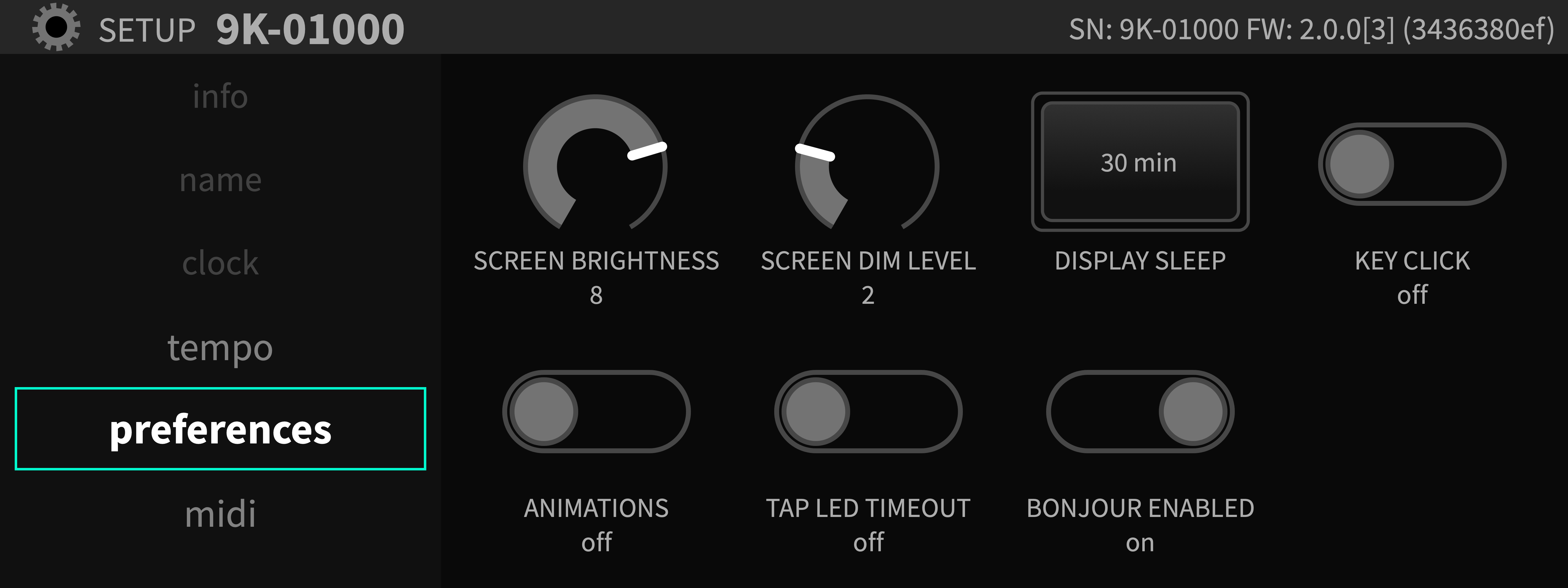
The Preferences section controls various aspects of the H9000’s display. Use the cursor keys to highlight the setting you wish to adjust, then use the Enter key and/or wheel to adjust the setting.
- Screen Brightness
This control adjusts the brightness of the front panel screen on a scale of 1-10.
- Screen Dim Level
This setting adjusts the brightness of the screen when it automatically dims after a selected amount of time, dubbed “Display Sleep”.
- Display Sleep
This controls the amount of time after which the display will automatically dim.
- Key Click
This setting toggles on/off an audible click when using the front panel buttons. The click is played from a small speaker located inside the H9000.
- Animations
By default, the H9000 offers assorted on-screen animations for the front panel display. This control toggles the animations on/off.
- Tap LED Timeout
By default, the front panel Tap button flashes in time with the tempo you have set using the front panel Tap button. Change this setting to “On” if you wish the button to stop flashing a few moments after you have set the tempo.
- Bonjour Enabled
Turning this setting to “On” configures the H9000 to advertise its services using the “Bonjour” protocol on the local area network. Bonjour is a zero-configuration network protocol that allows the H9000 to be automatically discovered by the Emote software, and should generally be left enabled for most network configurations.
3.1.7. Pedals
The H9000 allows connection of up to four independent foot pedals; these pedals can be a “switch” type (on/off) or a “continuous” type (volume) pedal.
When setting up an FX chain and its underlying algorithms, you can map the action of the footswitch/foot pedals to any parameter of your choosing, allowing expressive control of the effects. For example, a guitar player can control the cutoff frequency of a resonant filter using a foot pedal, while playing their instrument.
The Pedals setup page allows you to configure your unit for a wide variety of different types of pedals available in the marketplace, taking into consideration factors such as:
On/Off Switch vs. Continuous pedal
How many switches are on the foot pedal, which can range from none to as many as three switches per pedal
“Polarity” of the attached pedal
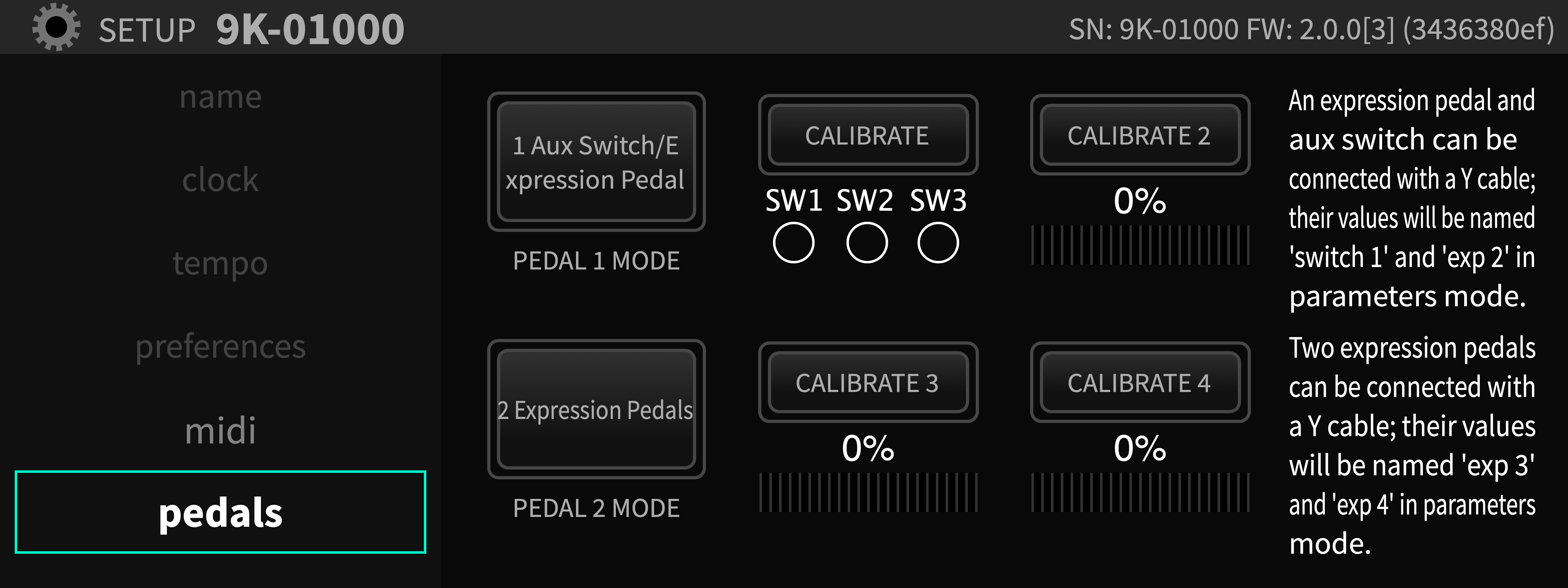
3.1.7.1. Configuring your Attached Pedal
Use the cursor buttons to highlight the “Pedal 1 Mode” or “Pedal 2 Mode” mode.
Press the Enter key, then use the cursor keys or wheel to navigate among the pop-up menu of options. Available choices include:
Expression Pedal
2 Expression Pedals
1 Expression Pedal + 1 Aux Switch
1 Aux switch + 1 Expression Pedal
2 button Aux Switch
3 button Aux Switch
After you have selected the mode appropriate for your connected switch/pedal, press the Enter key to save your selection.
3.1.7.2. Calibrating Your Attached Pedals and Switches
Once you have selected your desired type of pedal/switch, the H9000 will populate the rest of the display with relevant calibration tools.
Use the cursor button and the Enter key to navigate to and engage the “Calibrate” field.
If you have attached an on/off type pedal, physically press each switch and make sure that you see the appropriate “SW” circle illuminate. There are separate SW circles for 1, 2, or 3 button pedals. 3 SW circles are shown for 1, 2, or 3 button pedals because even a single aux switch may not be sent out as SW1 but may instead be sent out as SW2.
If you have attached a continuous foot pedal, navigate to the “Calibrate Pedal” field, then sweep the pedal back and forth with your foot. You should see the Calibrate Pedal field display a range between 0-100% on the calibration meter.
When you’ve finished calibrating, disengage the “Calibrate” button using the Enter key.
Even though there are only two pedal/switch connectors on the H9000, you can connect up to four pedals. This is made possible by connecting two pedals to each connector using a “Y” cable: https://etide.io/TRS
This capability is possible because:
In the external control section of the Parameters mode, there are 4 expression pedals listed.
In set-up mode, there are options to configure a single connector to be connected to two separate expression pedals.
3.1.7.3. Control Voltages
The H9000 can also be controlled using up to 4 control voltage sources. To do so, follow the instructions for setting up multiple expression pedals using a “Y” cable. CV 1+2 will correspond to the TIP and RING of Expression Pedal 1, CV 3+4 will correspond to the TIP and RING of Expression Pedal 2.
3.1.8. MIDI
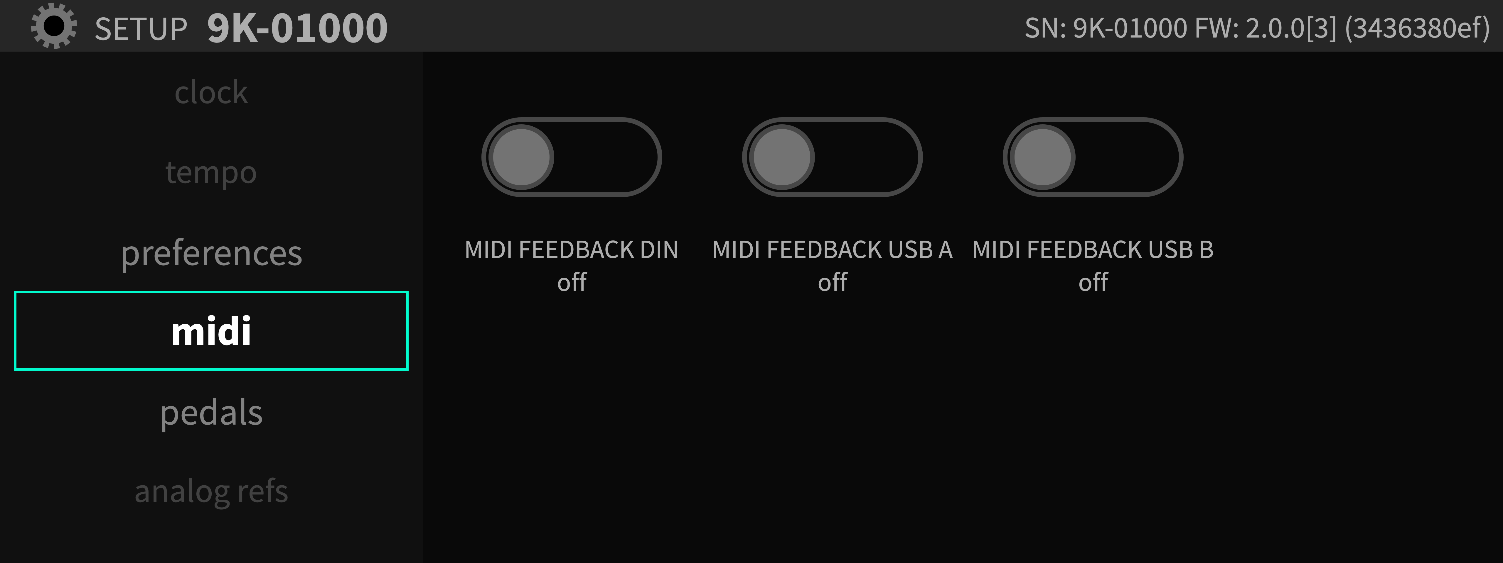
The MIDI menu displays options to enable and disable MIDI feedback.
- FEEDBACK DIN
Sends MIDI from the MIDI-in DIN jack directly to the MIDI-out DIN jack.
- FEEDBACK USB A
Sends MIDI from MIDI controllers plugged into the USB-A ports back to those very same MIDI controllers.
- FEEDBACK USB B
Sends MIDI from a USB host plugged into the USB-B port back to the very same USB host.
3.1.9. Analog References
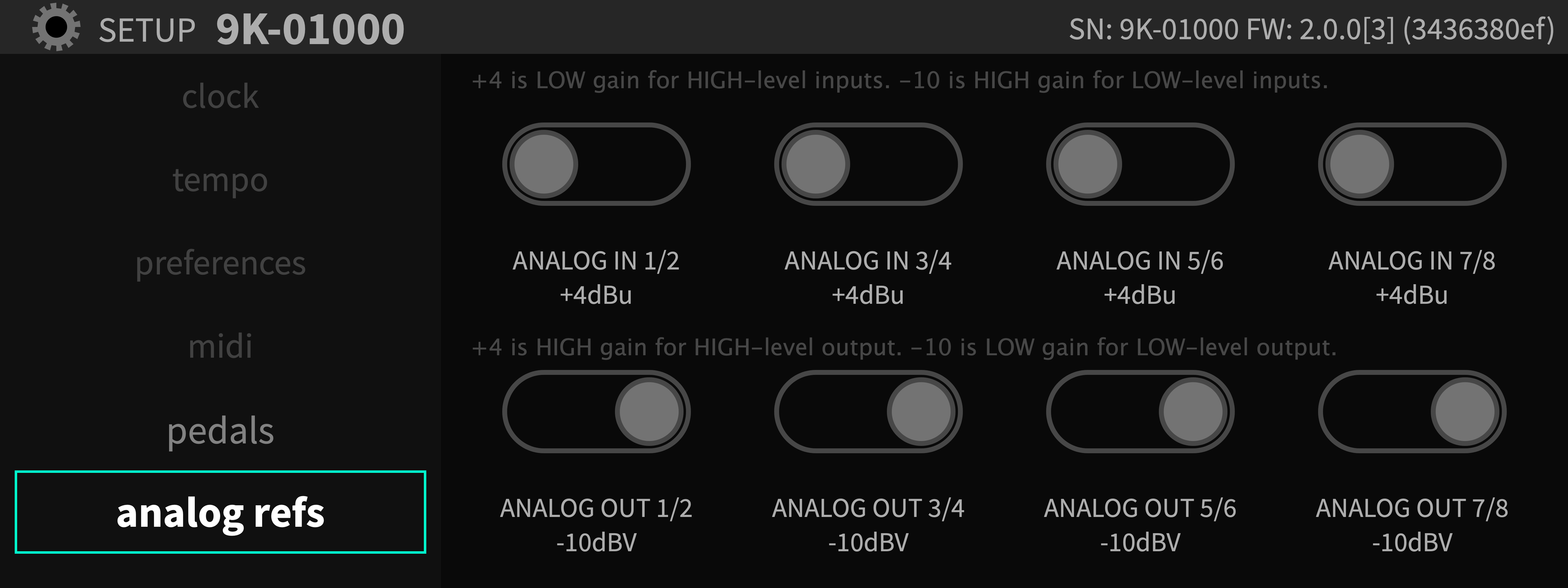
The Analog Reference Levels screen allows you to set the levels for the eight analog inputs and outputs present on the DB-25 connectors. This allows the H9000 to be installed in a wide variety of environments, and interface at an optimum level with professional and some consumer equipment.
Each pair of analog inputs and outputs on the DB-25 connectors can be separately selected between -10 dBV and +4 dBu.
Use the cursor buttons to highlight the specific pair of inputs or outputs you wish to adjust. Options include:
|
|
|
|
Once you have highlighted the appropriate pair of inputs or outputs, press the Enter button to switch to the alternate operating level.
Note that the rear panel XLR analog connectors are a duplicate “mult” of channels 1-2 of the eight-channel analog DB-25 connectors. As a result, any reference level changes made to analog input or output 1-2 of the DB-25 connector will also affect the XLR inputs and outputs.
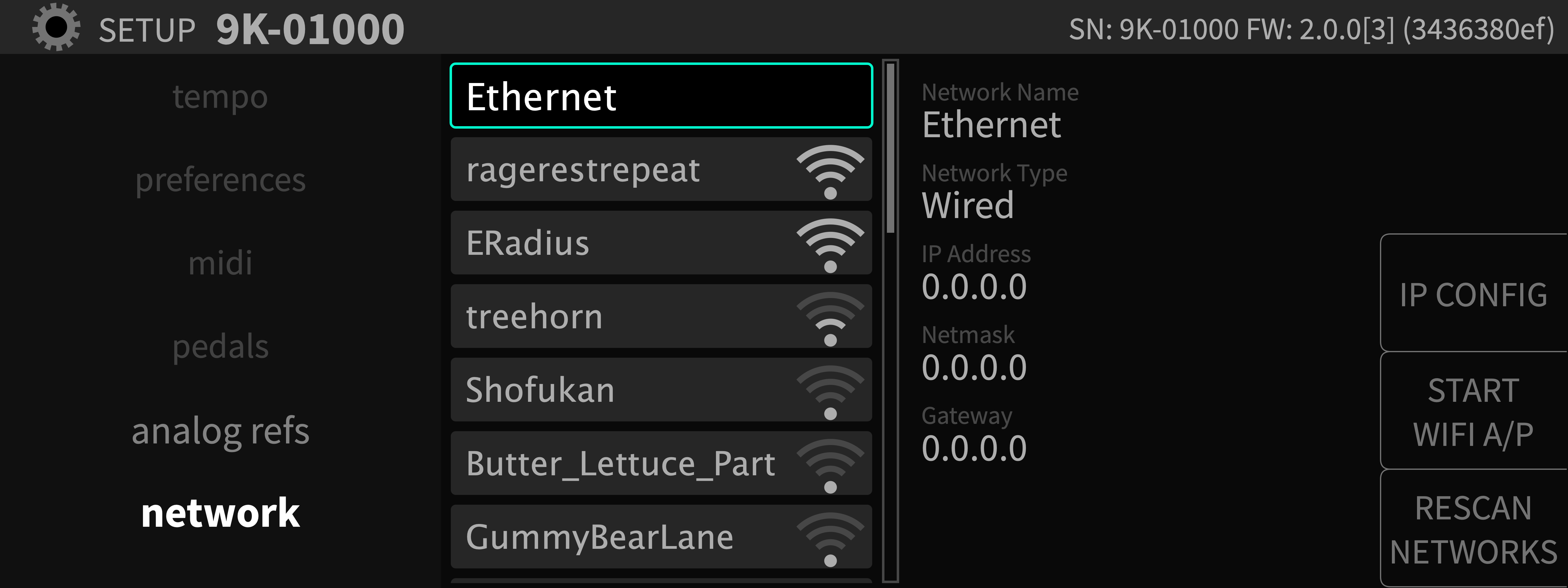
3.1.10. Network
The network screen controls settings for connecting your H9000 to a standard local area network. Once a network connection is established, you can use the Emote software to view and control H9000 parameters and update your H9000’s firmware.
The middle column of the network screen shows the available network connections, including:
Ethernet (for a hard-wired connection directly to the computer, or through your local area network)
Wireless (for a connection using the included Wi-Fi adapter, which can be connected to any of the four USB connectors)
3.1.10.1. Ethernet Setup
Use the cursor buttons to highlight the Ethernet field in the middle column. The right-hand column will display the parameters of the network you have joined including:
|
|
|
3.1.10.2. Wireless Setup
To connect the H9000 to a wireless network:
Connect the included Wi-Fi adapter to one of the H9000’s four USB ports.
On the network screen, any available wireless networks will be automatically listed beneath the Ethernet option.
Navigate to the wireless network that you wish to connect to and press the Enter key.
If the network is not password protected, you will be connected to the wireless network.
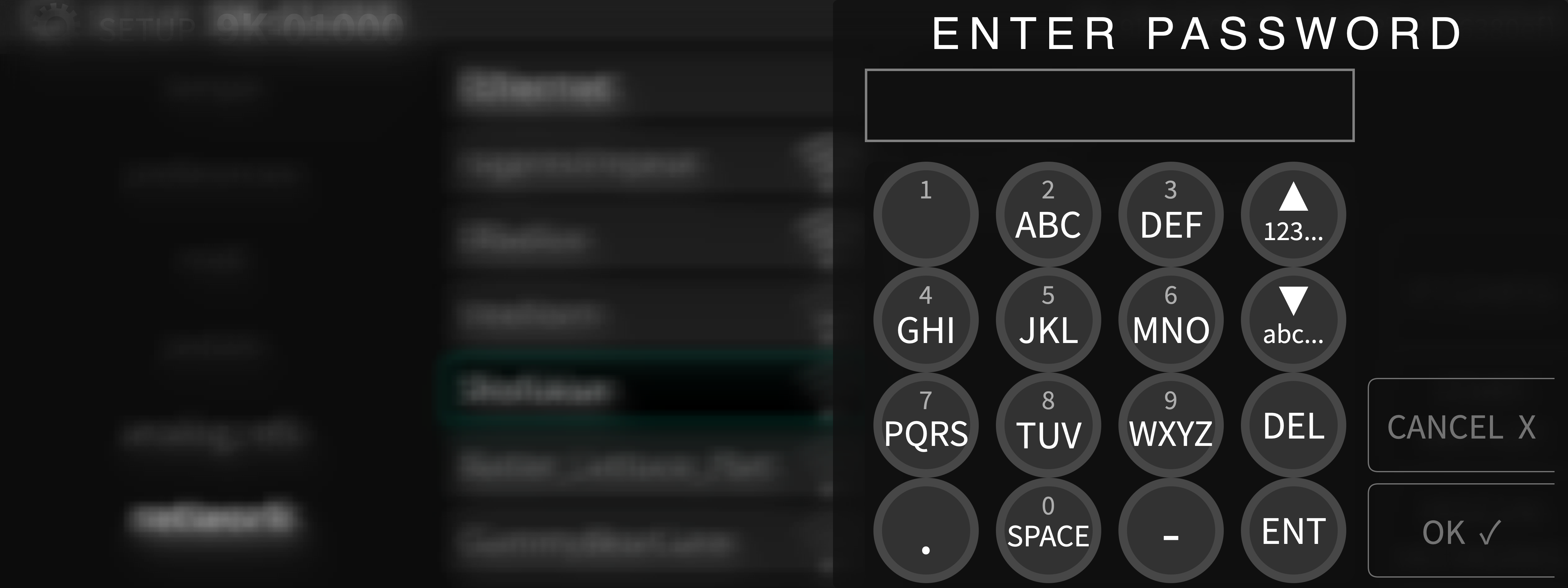
If the network is password protected, you will be prompted to enter the appropriate password. Use the front panel numbers pad to enter the password, then press the OK soft key.
You will then be connected to the wireless network, and can use the Emote software to control the H9000.
Note that the H9000 stores the authentication settings for the most recently joined network, so if you lose connection for any reason, you can re-join the network without having to enter your password again.
3.1.10.3. Network Configuration
To change your H9000’s network configuration, press the IP CONFIG soft key. Choose “DHCP” to initiate a request for an IP address, or “Manual” to configure a static address.
Note
Your H9000’s network configuration settings will be set to DHCP as the default setting and will not require further configuration in most situations. Manual IP addressing should only be used if there is no DHCP server on the network, or the DHCP server is configured to exclude a range of manual addresses.
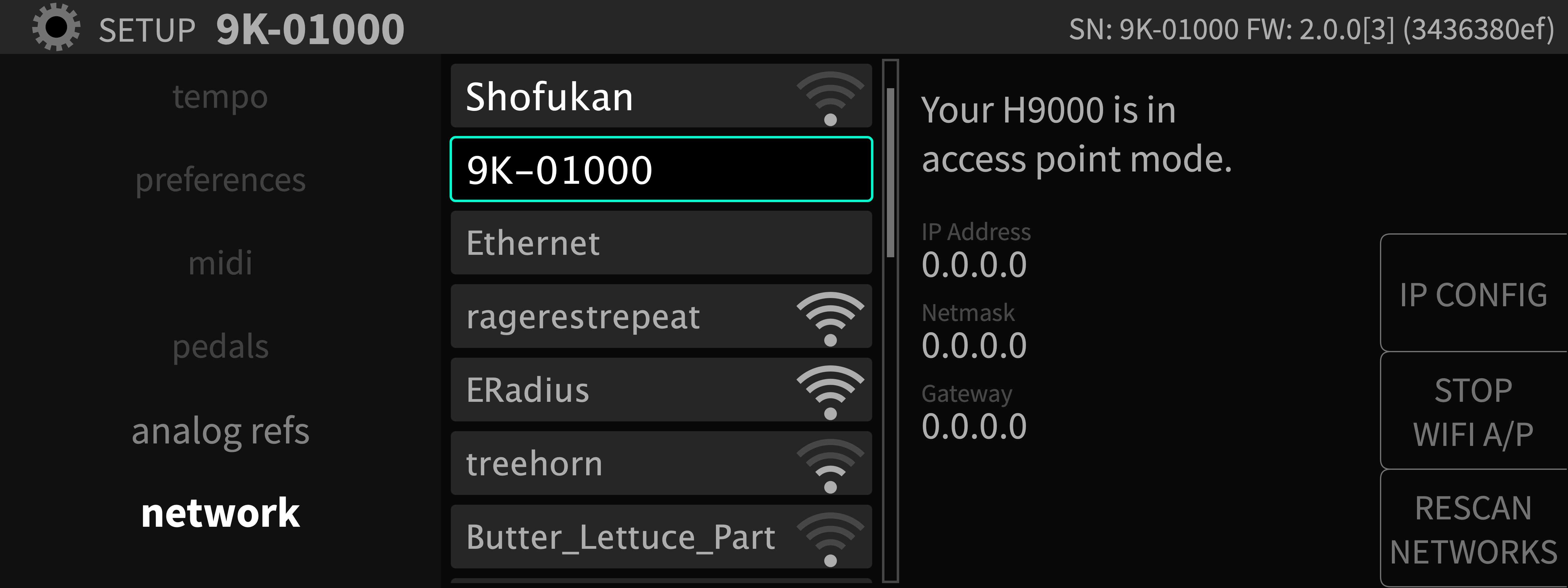
3.1.10.4. Creating a Local Access Point
The H9000 also has the ability to create and broadcast its own Wi-Fi network, called an “access point”. You can use the Emote software with the H9000 on this private network in environments where there is no LAN for the H9000 and the computer running Emote to connect to each other.
To create an Access Point:
Press the START WIFI A/P soft key.
You can choose to enter a custom password, or leave the password field blank.
If you leave the password field blank, a password will automatically be generated. This will be your H9000’s serial number in the format “9K-XXXXX”.
You will then see a message that the Access Point has been created.
The Wi-Fi access point will appear in your computer’s network settings as “H9000” followed by a string of automatically generated characters, or the custom name you have assigned to your unit.
Warning
Turn off the access point after you are finished using it. Otherwise it may interfere with Emote’s connectivity.