6.1. VSig
VSig is a visual editor used to create custom algorithms for the H9000. VSig utilizes a collection of precompiled code “blocks” known as modules, which are connected directly to one another to create patches. Algorithms can be uploaded directly and immediately to the H9000, with user definable UI objects (such as knobs and faders) which are viewable on the H9000’s front panel, or Emote.
6.1.1. Installation/Setup
VSig3 is available for download on the H9000/H9000R downloads page on the Eventide website.
To be able to download VSig, you must register your H9000 or H9000R serial number with your Eventide account. One registered, the VSig installer will become available for download.
To connect VSig to your H9000/H9000R, open VSig settings by navigating to File > Settings. An H9000 connection can be established using either the device’s IP Address or name. By default, the device name is its serial number in the format 9K-XXXXX. Both the device’s name and IP address are viewable and configurable in Emote.
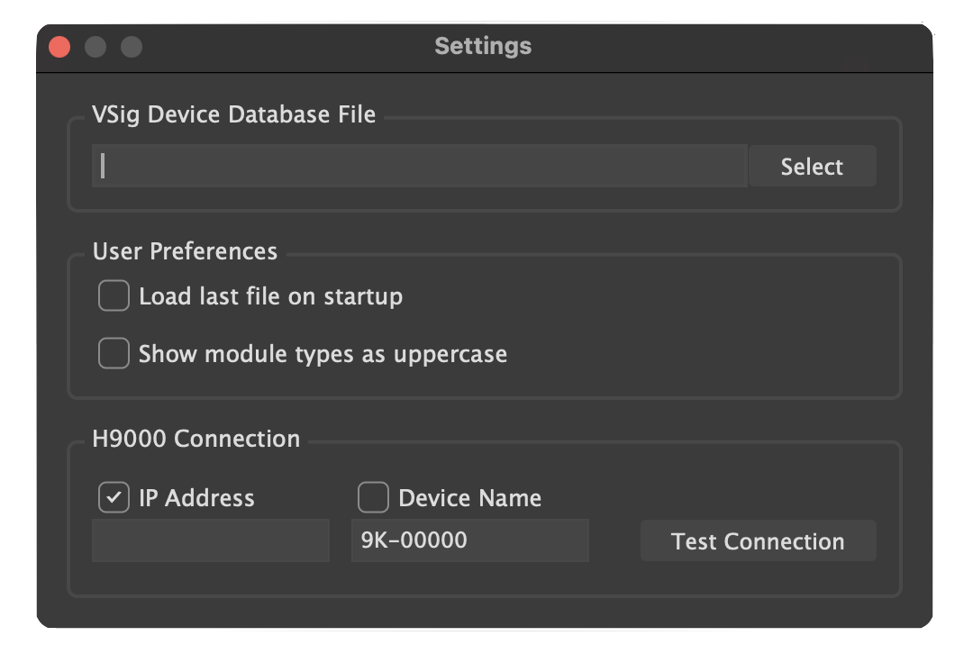
Fig. 6.1 VSig Settings
Once connected, you can begin uploading/downloading algorithms to/from the H9000.
6.1.2. Connection Types
There are 3 basic connection types used to create algorithms in VSig:
Signal (green) - used for sending audio signals
Control (blue) - used for sending control signals; often involves using interface modules to control parameters of other modules
User (pink) - used for GUI purposes; allows for the creation of menu pages, which display interface objects (such as knobs, faders, monitors, etc.) to users via Emote
6.1.3. Tool Bar Functions

Fig. 6.2 VSig Toolbar
Undo
Redo
Zoom in
Reset to default zoom
Zoom out
Zoom to fit
Hide/show signal connections
Hide/show control connections
Hide/show user connections
Increase/decrease opacity of modules
Download an existing algorithms VSig file from H9000
Upload algorithm either to first slot on FX chain, next empty algorithm location, or an algorithm location of your choice
AutoLayout algorithm
6.1.4. Modules
Modules are precompiled “blocks” of code which act as the building materials for all VSig algorithms. Modules are able to send and receive signals to and from one another by clicking and dragging from one module to another to establish connections.
Each module has documentation containing details about its functionality, inputs, outputs, and parameters. To access this, right click on a module, and select “Show Module Documentation.”
6.1.4.1. Module Types
Bridge – convert between signal and control connections
Controlmath – performs mathematical operations on control signals, including basic arithmetic, comparison, conversion, logical operators, etc.
Controlprocess – provides further methods for manipulating/operating on control signals
Delay – various forms of delaying/phase shifting an audio signal; includes modulatable delays, all pass filters, comb filters, etc.
Detector – read various quantities associated with audio signals and output them as a signal; can detect pitch, peak amplitude, envelope, etc.
Dynamic – used to modify gain/amplitude of an audio signal; includes compressors/expanders, gates, duckers
External – used for accepting signals from external control surfaces, such as MIDI interfaces or expression pedals
Filter – used for altering the frequency or phase response of an audio signal; includes standard filter/EQ modules which attenuate harmonics, in addition to objects which add harmonics (distortion)
Interface – used to create GUI objects that the user can interact with via the H9000, or within Emote if using H9000R
Math – performs mathematical operations on audio signals; includes many of the same modules as Controlmath, with some additions such as gain
Miscellaneous – self explanatory
Mixer – used for various signal routing purposes; includes standard mixers, in addition to switches, crossfaders, panners, etc.
Oscillator – generate waveforms, including envelopes, LFOs, impulses, noise, or other audible waveforms
Pitchshift – used for detuning/pitch shifting audio signals; includes several options depending on the required amount of pitch shifting, whether or not audio needs to be shifted diatonically, etc.
Reverb – includes “plug and play” reverb modules (Reverb_2016, stereo_room, and reverb_a,b,c,d) which can be used on their own without additional modules, in addition to modules which can be used to build reverb algorithms from the ground up.
6.1.4.2. Head Module
The head modules appear on the left and right of the editor UI, and are automatically generated when you create a new patch. It is used to route audio and control signal in and out of a VSig patch. It looks like this:
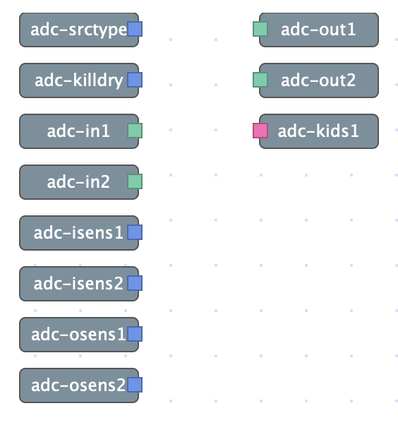
Fig. 6.3 Head modules generated automatically when creating a new VSig file
The list of head submodules is as follows:
adc-scrtype: Gives the current input source type [1=guitar, 2=bass, 3=lead, 4=sub]
adc-killdry: Gives the current killdry status
adc-in1, adc-in2: Audio input from corresponding adc channels (more adc-ins can be added in the module editor)
adc-isens1, adc-isens2: Gives the connectivity status of the corresponding adc input
adc-osens1, adc-osens2: Gives the connectivity status of the corresponding adc output
adc-out1, adc-out2: Audio output to corresponding adc channels (more can be added in the module editor)
adc-kids1: Output for UI object groups to emote (more can be added in the module editor.
6.1.4.3. Module Editor
The module editor is displayed on the right-hand side of the screen whenever a module is selected, and displays important information regarding parameters, connections, and objects associated with a module.
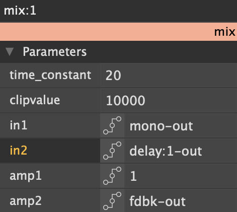
Fig. 6.4 Editor page for a mix module. All parameters are shown, including signal inputs and their associated amplitudes.
The module editor can be used to manually define parameters via text entry, or may show how a parameter is being controlled by an interface object. In the example above, amp1 is manually defined to have a value of 1, whereas amp2 is being controlled by the output of an interface module with the name “fdbk.”
in1 and in2 are both signal inputs which are receiving audio signals from other modules. in1 is receiving signal from a module named mono, while in2 is receiving signal from a module named delay:1.
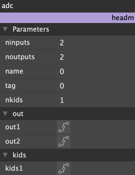
Fig. 6.5 The module editor also displays important information regarding the head module and its associated submodules. Clicking on any head submodule opens the editor pictured above.
6.1.4.4. Interface Modules and Creating UI
Interface modules are somewhat unique in that they only utilize control and user connections, never audio signal connections. Control connections are used to send control signals which target parameters of other modules. User connections are used to make interface modules visible within Emote, allowing for the creation of custom GUI.
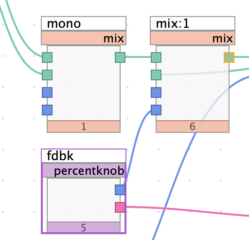
Fig. 6.6 Percentknob module connected to mix module via control connection
A small section of a patch shown above demonstrates the use of control connections. The output of the knob module labeled “fdbk” is connected to the amp2 input. When viewable in Emote, the knob’s position at any given time corresponds to a value which determines the amplitude level of input2. As mentioned above, this connection can also be seen in the module editor.
The range of values accessible by an interface and its resolution are both user definable. Min and max parameters are self-explanatory, while resolution determines the smallest possible discrete value by which an interface object can change.
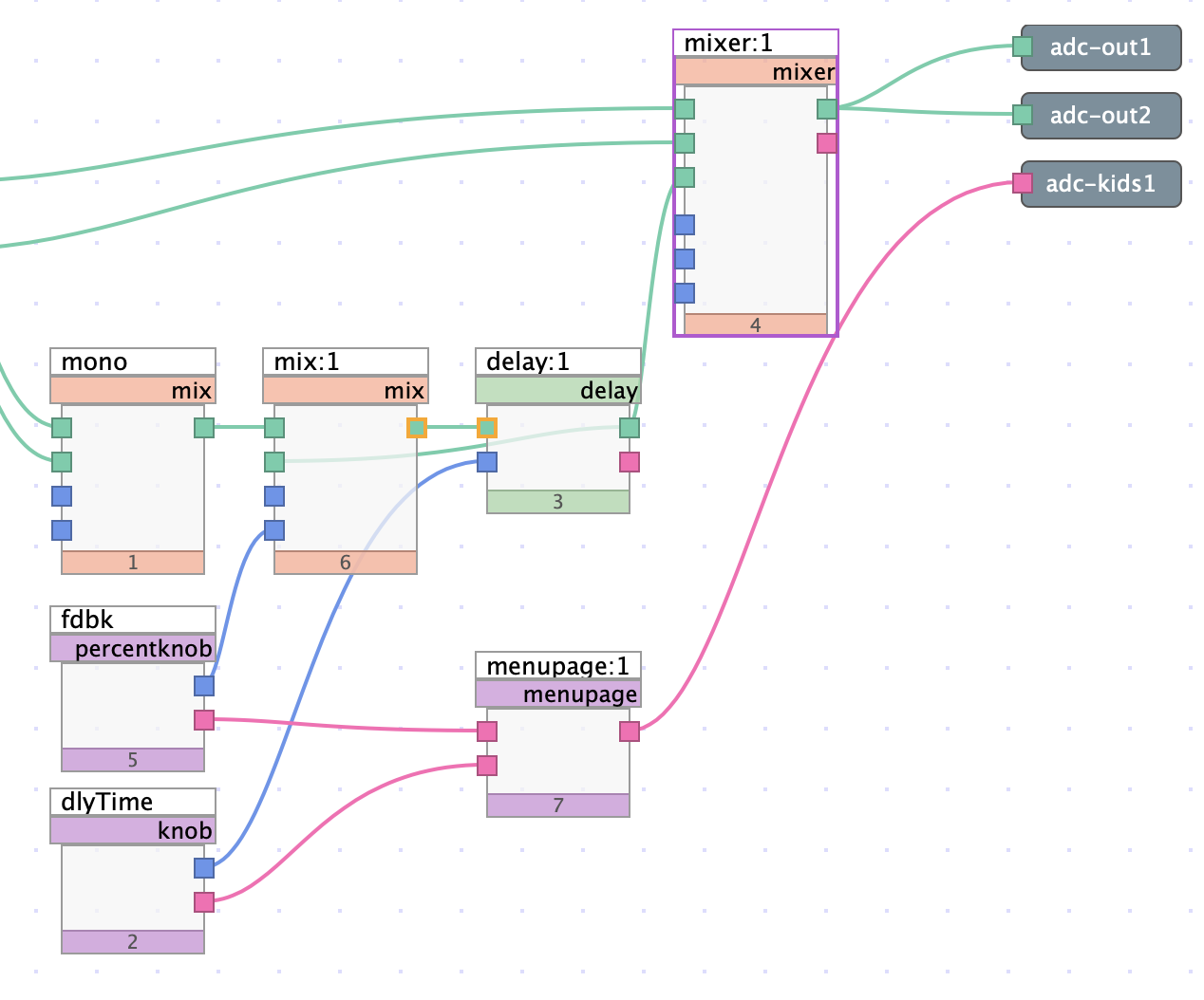
Fig. 6.7 Percentknob and knob module both connected to menupage module via user connections
For ANY interface module to be visible in Emote, it must be connected to a menupage module, which must subsequently be connected to adc-kids. The sample patch above shows two knob modules (fdbk and dlyTime) being connected as described above.
The module editor for most interface objects includes a “statement” field. Text entered in this field will be displayed to the user alongside the UI object in Emote. To display values which change in real time as you interact with the UI, the following syntax must be used:
Changing values are wrapped by the % and f characters. Text to be displayed under a knob should be placed before a colon (:).
Between the % and f should be a decimal number. The whole number portion of your decimal indicates how many digits will be displayed before the decimal point. The decimal portion indicates how many digits will be displayed after the decimal point.
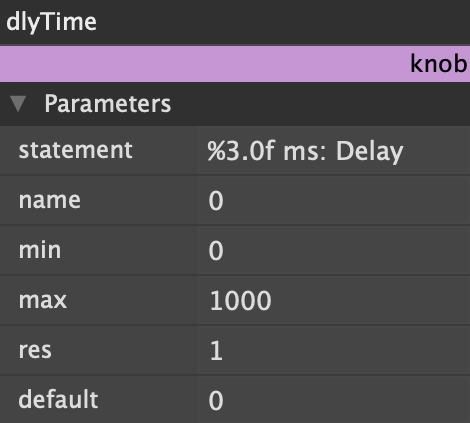
Fig. 6.8 Knob module utilizing %f syntax in its statement field
The example above will show a knob labeled “Delay,” and show the delay value, in ms, at each knob position, with up to 3 whole number digits and 0 decimal digits. (The %f syntax exclusively affects how values are displayed. It is possible to have an interface module which has higher resolution than is shown to the user)
Text outside of the %f indicators will be displayed as normal, unchanging text
UI design is explored in greater detail in Vsig Beginner Tutorial #4 - Intermediate Menu Design.
6.1.5. Downloading and Uploading Algorithms
To download an algorithm from the H9000 into VSig, click the icon with the downward arrow inside the cloud. Once downloaded, the user will be able to see exactly which modules are used on a preexisting algorithm and how they are connected. When learning VSig, downloading and reverse-engineering preexisting algorithms is a very effective way to begin learning how certain modules work and how modules may be connected.
To upload an algorithm from VSig to the H9000, click the icon with the upward arrow inside the cloud. Algorithms can be sent directly into the FX chain, or can be stored within Emote in any empty algorithm slot. Once uploaded, algorithms can be tested immediately.
6.1.6. Basic Delay Algorithm
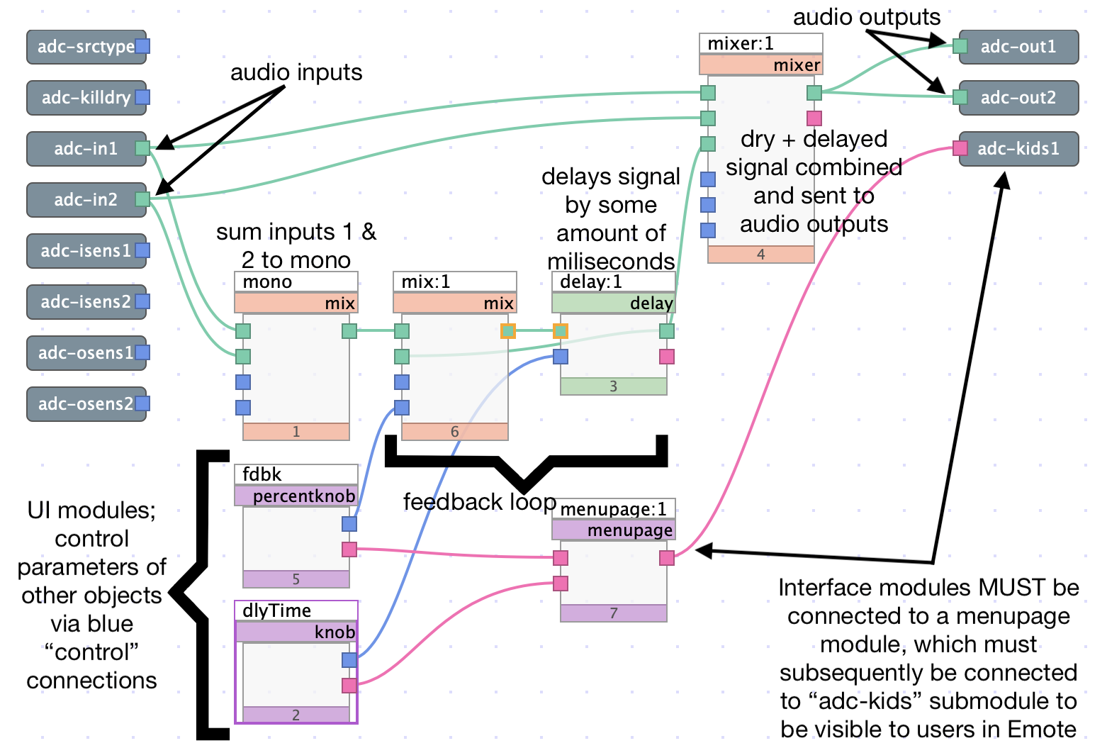
Fig. 6.9 Simple delay algorithm
The algorithm shown above is a simple delay, intended to demonstrate how modules may be connected to one another to create audio effects. The audio inputs, labeled adc-in1/2, are first split into a dry path and a delay path. The dry path is routed straight to a mixer, which is sent directly to the audio outputs.
The delay path first utilizes a mix module which sums the two inputs into a singular output. The signal is then sent to another mix module followed by a delay module. The combination of the mix and delay modules not only allows the signal to be delayed by a user definable time, in milliseconds, but also feeds the delay signal back to its input to create a feedback loop. The delay output is also routed to the mixer, combining it with the dry signal.
6.1.7. Legacy Support
The current version of VSig, VSig3, is only available for H9000 and H9000R owners and is only compatible with those devices. Several legacy rackmount devices, however, continue to offer support for VSig2. These devices include:
H8000 family (H8000, H8000A, H8000FW)
H7600
Orville
DSP family (DSP7000/7500, DSP4000B+)
Those who would like to develop algorithms for any of the above devices may refer to the following resources:
VSig2 functions quite similarly to VSig3 with some variance. The minutiae of this variance will be revealed to those who choose to dive deep into VSig2 development, but several key differences are as follows:
VSig2 is only available on Windows machines (Mac users may find success with virtual machines, but Eventide is unable to assist in replicating such a setup)
VSig2 requires that a device connection be established via a MIDI interface or serial connection, as opposed to VSig3’s WIFI/Ethernet connection
VSig2 utilizes a tool called the “VSig Specifier Display,” which is an equivalent to VSig3’s module editor. The VSig Specifier Display can be opened by double-clicking on a module.
To add modules to your VSig2 patch, you must use the “Add Module” command in the “Edit” menu. Modules are slightly more “hidden” than in VSig3, which constantly displays the module library on the left side of the screen.
Legacy rackmount gear does not have companion software like H9000’s Emote. Because of this, UI should be designed for the device’s built-in display (see pages 45-47 of the Programming Manual for in depth assistance with menu design)
VSig2 includes a “supermodule” function, allowing several modules to be subsumed into a single supermodule which can be saved to the library (pages 57-61 of the Programming Manual)
Any other subtle variations between VSig2 and VSig3 will likely be revealed through use, or by reading the Programming Manual. Despite the differences listed above, core functionality is nearly identical between VSig2 and VSig3, making it easy to begin developing with one if you are already familiar with the other.