6.4.4. RNBO Tutorial #3 – Simple Gain with Filters
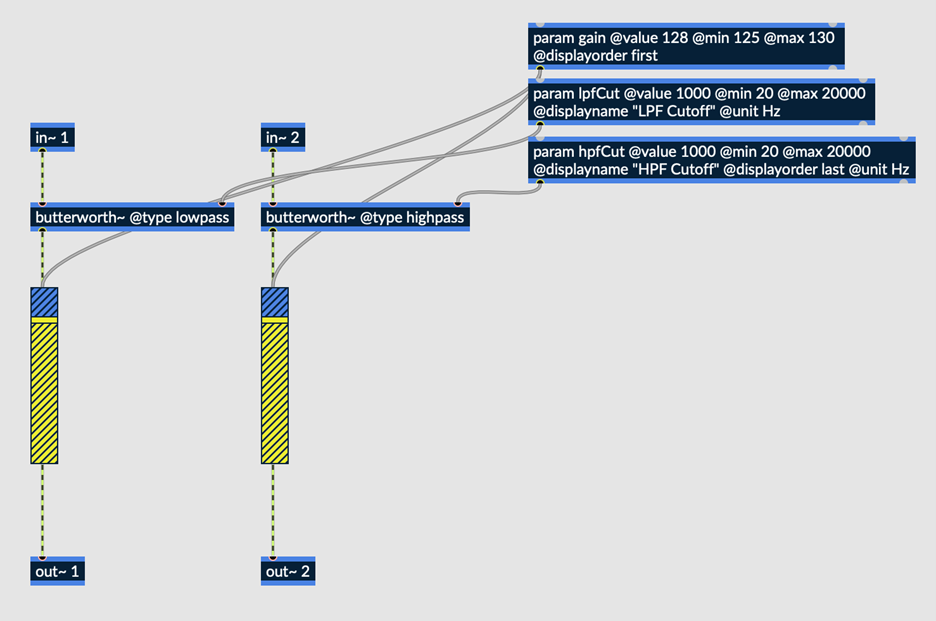
Fig. 6.79 Simple gain, with low and high pass filters applied to the left and right channels respectively
The above patch continues to expand upon Beginner Tutorials #1 and #2, this time demonstrating how each audio input may be processed completely independently of the other. The butterworth~ filter object in this case is used to process input 1 with a low pass filter, while input 2 is processed with a high pass filter.
Download the maxpat file here: Simple Gain with filters.
6.4.4.1. Butterworth~ Objects
Butterworth~ is a filter object which can act as either a low or high pass filter depending on its @type attribute. Butterworth refers to a type of analog filter with maximally flat frequency response in the pass band.
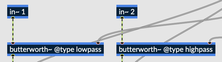
Fig. 6.80 Inputs 1 and 2 both routed into butterworth objects
In this patch, input 1 is processed by a butterworth~ object with a “lowpass” @type attribute, meaning it acts as a lowpass filter. Similarly, input 2 is processed by the same object with a “highpass” @type attribute, meaning it acts as a highpass filter.
While maybe not the most practical effect, the goal of this patch is to demonstrate how each audio input may be processed completely separately from and independently of the other inputs.
6.4.4.2. Gain~ Objects
Unlike the first two beginner tutorials, this patch utilizes two identical gain~ objects, one for each input. Now that each input is being processed differently, they must both have their own gain~ object to avoid summing both inputs to a single output signal. Notice, however, that the gain param object simultaneously controls both gain~ objects, providing the end user with a single gain control for both channels.
6.4.4.3. Param Objects
Two param objects have been added to the patch, both controlling the cutoff frequency of each filter object. As you may have noticed, new arguments are being used on these param objects. Let’s look a little deeper:
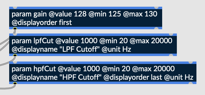
Fig. 6.81 Param objects, controlling gain, LPF cutoff frequency, and HPF cutof frequency
As previously discussed, @value, @min, and @max designate the parameter’s default, minimum, and maximum value respectively.
Displayname
@displayname is used to designate how the knob will be labeled in Emote, or in any external environment which the patch has been uploaded to.
Displayorder
@displayorder is used to designate the order in which parameters will appear in an external environment. Order can be specified numerically, or symbolically using the keywords ‘first’ and ‘last.’
Unit
@unit is used to describe the unit of a parameter in an external environment and will be displayed next to its numerical value.
With all these attributes being used, the UI within Emote looks like this:
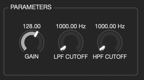
Fig. 6.82 UI displayed in Emote, containing 3 knobs
Notice that the filter cutoff frequency knobs are labeled using their @displayname attribute, as opposed to the name of their param objects. These knobs also both include units, in this case Hertz (Hz) next to their numerical values. Finally, the knobs are displayed, from left to right, in the order of “Gain,” “LPF Cutoff,” and “HPF Cutoff,” which is congruent with our @displayorder attributes.
Upon exportation to Emote, the three knobs shown in the screenshot above will be displayed to the user. The “gain” knob is unchanged from the previous two tutorials, although this knob now technically controls two separate gain~ objects, one for each channel. The “LPF Cutoff” and “HPF Cutoff” knobs control the cutoff frequency of low and highpass filters. As previously discussed, our signal routing in RNBO is set up such that the lowpass filter only affects input channel 1, and the highpass filter only affects input channel 2.