6.4.9. RNBO Delay Tutorial #2 - Stereo Flanger
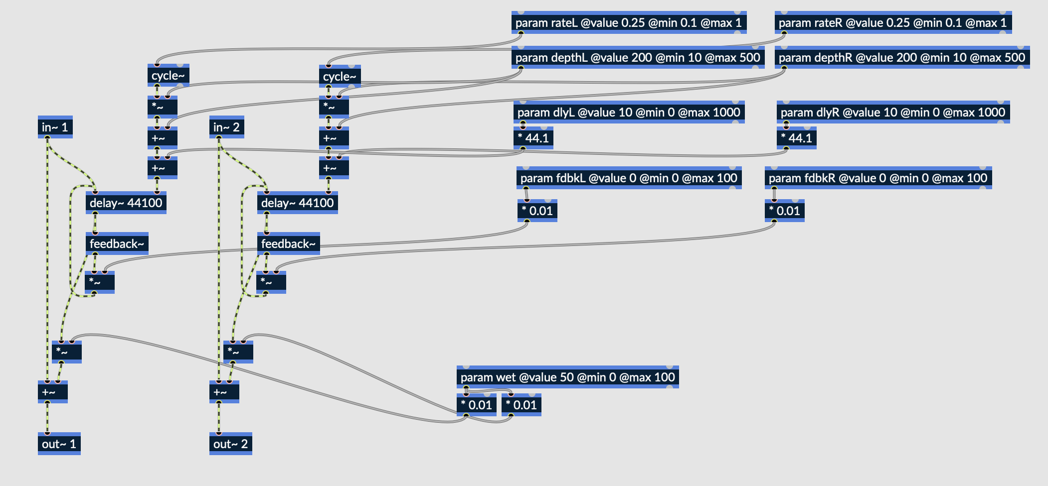
Fig. 6.100 Stereo flanger patch in RNBO
The above patch expands upon the Stereo Delay patch from the last tutorial. Not only are the parameters present in the last patch split into individual controls for the left and right channels, the delay lines are now modulated to create a flanging effect. The addition of modulation necessitates the introduction of the “rate” and “depth” parameters, both of which can be individually controlled for each channel.
Download the maxpat file here: Stereo Flanger.
6.4.9.1. Modulated Delay Structure
The delay lines themselves are unchanged from the Stereo Delay patch, but the delay time input now varies overtime. The cycle~ object acts as the main delay input, which outputs a sine wave. The frequency of the sine wave is controlled by the “rate” parameter. For the sine wave to behave exactly how we want it to, some basic operators are used.
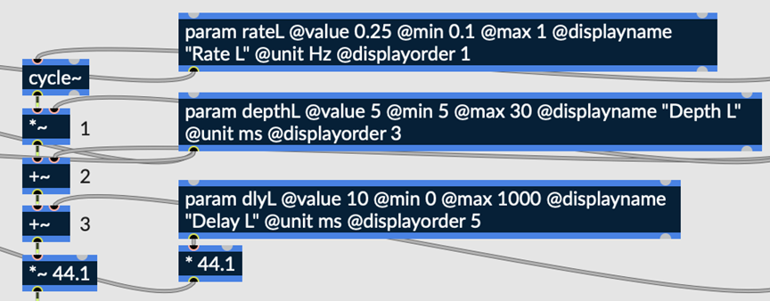
Fig. 6.101 Modulated delay structure
1. The sine wave first has its amplitude scaled by constant factor, which is controlled by the “depth” parameter.
2. The amount of depth is then added to the sine wave output so that the output is always positive.
3. Finally, another constant is added to the sine wave, controlled by the “delay” parameter. This effectively acts as a delay offset, if the user desires an initial delay to the signal in addition to the flanging effect.
The output is ultimately multiplied by 44.1 for the same reason the delay param is multiplied by 44.1 (see Delay Tutorial #1 for more details).
Before performing these operations, the output of cycle~ will look something like this:
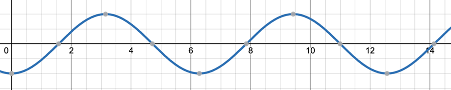
Fig. 6.102 Graphical representation of cycle~ output, before performing the above operations
The result of these operators will cause the wave to look something like this:
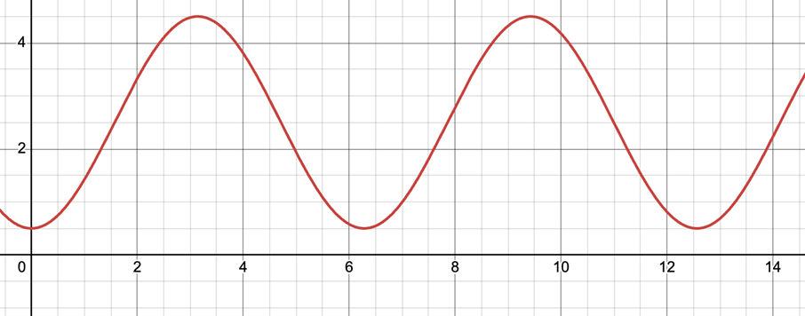
Fig. 6.103 Graphical representation of cycle~ output, after performing the above operations
Operator #1 scales the wave’s amplitude, while operator #2 vertically shifts the wave by the same amount that its amplitude was scaled. With only these two operations having been performed, the wave varies in output between 0 and double its amplitude. Finally, operator #3 provides an additional vertical shift. The result is a unipolar sine wave with some amount of vertical offset.
Recall that this sine wave represents the amount by which a signal is delayed as a function of time. The physical interpretation of this function, as previously discussed, is a delay line with a constantly changing delay time.
6.4.9.2. Additional Delay Parameters
Two new parameters, depth and rate have been added to this patch. Also, all parameters in the last patch have been doubled to allow independent parameter control over the left and right channels. We have already explored in detail how these parameters are utilized within the patching environment, but it may be helpful to describe these parameters more generally:
Depth – the amount of delay modulation, measured in milliseconds; in other words, the amount by which the delay is allowed to fluctuate
Rate – the rate at which delay fluctuates, measured in Hertz; the greater the rate and depth, the more intense the flanging effect tends to be.
Although the “delay” parameter was present in the last patch, it now behaves somewhat differently. Instead of acting as the time between the onset of the original signal and the delayed signal, it acts as the time between the onset of the original signal and the flanged signal. The difference is subtle, but worth acknowledging.
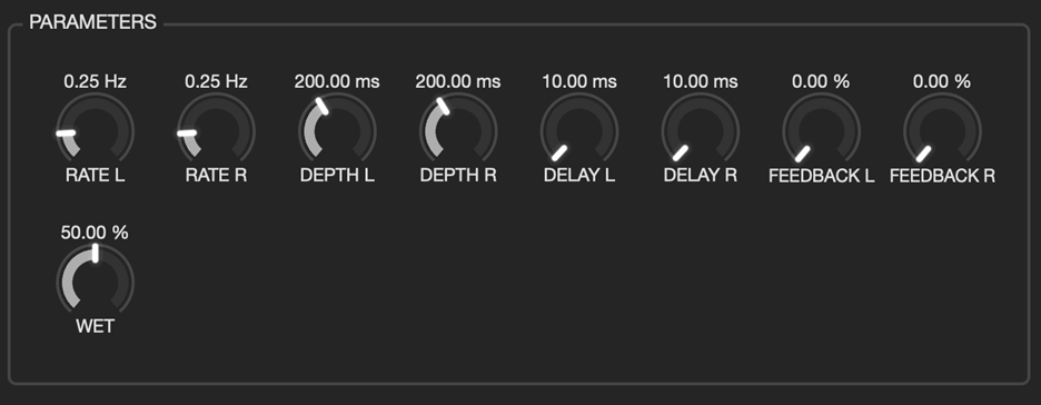
Fig. 6.104 UI displayed in Emote
Upon exporting to Emote, the above menu will be displayed to the user. With minimal additional patching, the original Stereo Delay effect has been upgraded to a Stereo Flanger with independent control of parameters for each channel.