6.4.1. Max/RNBO Tips for the H9000 User
Max is a visual programming environment for DSP/multimedia projects. RNBO is a Max extension that allows users to build and export patches to external plugin formats.
Working in RNBO is very similar to Max, with some key differences. The first section of this guide will cover basic functionality shared by RNBO and Max. In the second section, we’ll take a closer look at RNBO and how it works alongside Max.
This guide will cover the basics of Max signal flow and syntax, and give tips for the H9000 user who is familiar with VSIG looking to get started working in Max/RNBO. It is intended to help those with some DSP experience who are new to Max.
Tip
For more detailed guides, tutorials, and documentation for Max/RNBO, check out the resources over on cycling74’s website:
To talk with other VSIG/H9000 users, check out the Eventide user forums at:
Finally, Max’s built in help and reference files are excellent resources for troubleshooting and finding examples for each object. To access them, right click an object and choose ‘Open [object] help’ or ‘Open [object] reference.
6.4.1.1. Audio vs. Data
Like VSig, Max handles primarily handles two kinds of signal—audio and data signals. Audio signals are carried by striped green patch cables, while data signals are carried by gray patch cables. Objects that carry audio signals (MSP objects) end with the ‘~’ symbol. See the examples below.
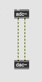
Fig. 6.54 Audio signal cables
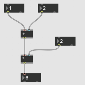
Fig. 6.55 Data signal cables
Keep in mind that many objects have multi-function inlets (often the inlet furthest left). Sometimes, the same inlet can take an audio and data signal at the same time.
Tip: To send/enable objects to accept floating points, a decimal point must be included at the end of your argument. Otherwise, Max will interpret it as an integer.
6.4.1.2. Bang
The ‘bang’ message is one of the most important features in Max. When an object receives a bang, its output is triggered. Bangs can be sent in a number of ways, the simplest being the bang button, a gui object that bangs when clicked. Many objects also output a bang when once their operation is complete. This is especially useful for creating networks of ordered events and processes in your patch.

Fig. 6.56 Button that outputs a bang when pressed
A bang produces a single instantaneous trigger. For switching and holding (for example, turning on the [count] object), objects take a binary value.
6.4.1.3. Audio Routing
To select your audio device in Max, go to Options>Audio Status. From this menu, you can change your input and output devices, adjust the sample rate and i/o vector, and customize your channel routing.
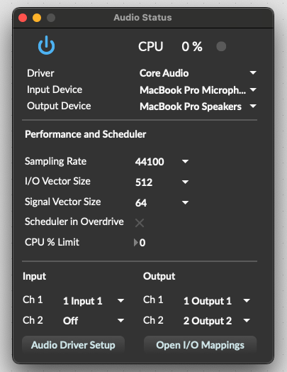
Fig. 6.57 Audio Status window
Note
Max does not automatically follow your current system audio routing. If your system is connected to an external audio interface and you want to connect Max to that interface, you must do it manually each time you launch Max. Typically, Max will connect to your internal computer mic and speakers by default. If you forget to change the device, this can lead to some nasty feedback.
The [adc~] and [ezadc~] objects bring audio into Max. The [adc~] object must be given arguments for each channel. By default, [adc~] is set to channels 1 and 2. If you wanted it to take channels 1-4, you would enter the channel numbers as sequential arguments:
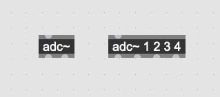
Fig. 6.58 [adc~] objects
[ezadc~] is a gui object that inputs only from channels 1-2.

Fig. 6.59 [ezadc~] object
The same applies to the audio output objects, [dac~] and [ezdac~]. All four of these objects can be used to turn audio on/off, either with a binary input or by clicking on the gui objects. The button in the bottom right of the Max window is blue when audio is on, and gray when it is off.
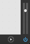
Fig. 6.60 Audio on, indicated by blue power button
6.4.1.4. Patch Cables
Objects are connected in Max using virtual patch cables. To do this, click and hold on an object outlet and drag it over to an inlet. To make connections without patch cables, you can use [send] and [receive] objects. These are helpful for sending a message to many places at once, as well as communicating between subpatchers.
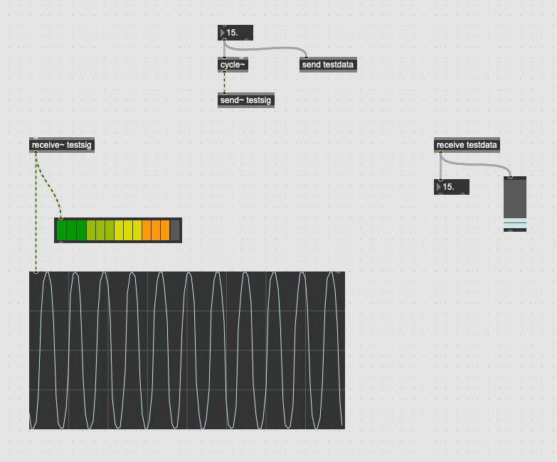
Fig. 6.61 Basic Max patch demonstrating [send] and [receive]
For convenience, send and receive objects can be abbreviated as [s~], [r~], [s], and [r].
6.4.1.5. The Console and Inspector Windows
The console and inspector windows are important tools for debugging your patch and adjusting advanced object parameters/UI settings. They can be opened via the right menu pane in Max and RNBO. Inspector can also be opened with the cmd+i (Mac) or ctrl+i (Windows) keyboard shortcuts.

Fig. 6.62 Console

Fig. 6.63 Inspector
The Max console displays various system messages, including errors, package information, and values printed by the [print] object. The console is useful for testing and debugging your patches.
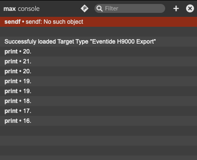
Fig. 6.64 Console window
The inspector window lets you edit various functional and UI settings for Max objects. Select an object in Max, and its settings will appear in the inspector window. In the example below, you can change settings for the number object, including its min and max values, font, size, color, and more.
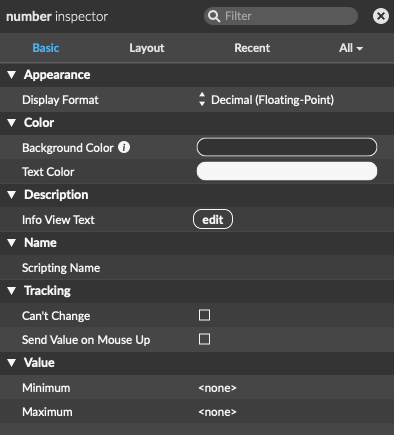
Fig. 6.65 Inspector window
6.4.1.6. RNBO Signal Flow
To create a RNBO subpatcher, enter the [rnbo~] object in Max. This will generate a new RNBO patching window. RNBO objects are distinguished visually from Max objects by their blue border.
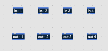
Fig. 6.66 RNBO objects with blue borders
RNBO does not have built in adc/dac objects. Audio must be routed from the container Max patch into RNBO. To do this, you’ll need to create [in~] and [out~] objects in RNBO. A positive integer argument must be defined, and arguments cannot be repeated, even between audio and data ins. For example, you can’t have [in~ 1] and [in 1] in the same RNBO patch. These ins and outs will appear as inlets and outlets on the [rnbo~] object in Max.
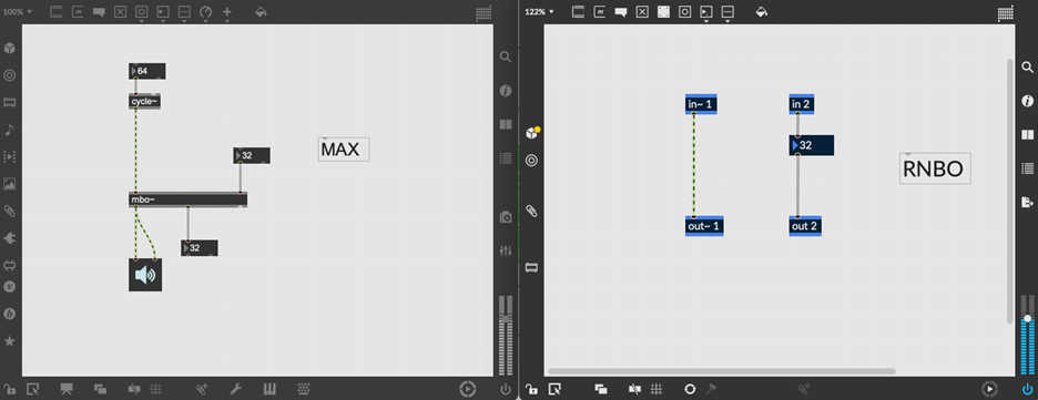
Fig. 6.67 Max objects with gray borders shown on left. RNBO objects with blue borders shown on right.
6.4.1.7. Using Parameters
One of the most important tools in RNBO is the [param] object. This object allows you to define parameters in your RNBO patch and control them externally. Parameters are converted to controls in Emote when exporting RNBO patches to the H9000.
Note
Without parameters, you will not be able to adjust any controls on your patch once it is exported to the H9000.
To create a parameter, create a [param] object in RNBO with a name argument:
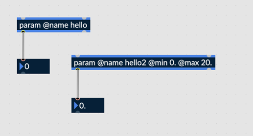
Fig. 6.68 Two [param] objects, named “hello” and “hello2”
You can also define arguments for the minimum and maximum values the parameter will accept. In the example above, the ‘hello2’ parameter is set to accept float values between 0 and 20.
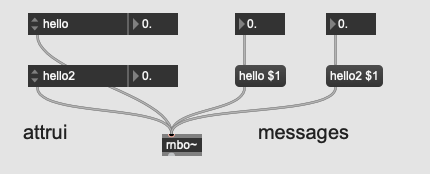
Fig. 6.69 Controlling parameters in Max
The simplest way to control a RNBO parameter in Max is with the [attrui] object. When connected to the [rnbo~] object, it will show all available parameters in its dropdown menu. You can also send RNBO a message with the parameter name and value. In the example above, the float boxes send a value to the $1 variable object in each message box and trigger the message output. You can see that the values have been received in the RNBO patch.
For more information on parameters, refer to the [param] help patch in RNBO.