6.2.1. VSig Beginner Tutorial #1 - Simple Gain
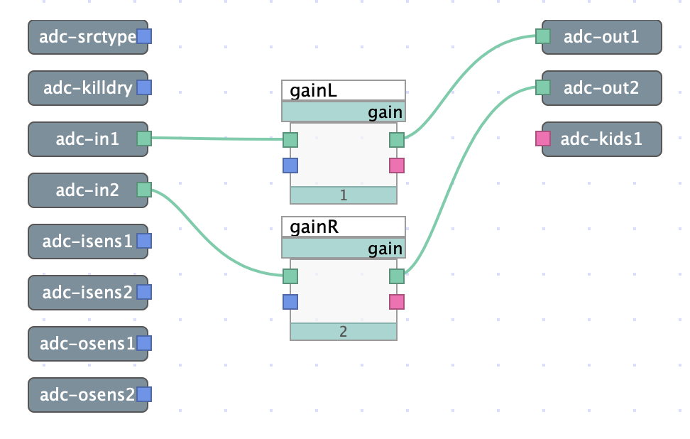
Fig. 6.10 Simple gain algorithm with no user control
The above patch is designed to show how audio signal is routed in VSIG using two gain modules. By clicking and dragging from a green signal output to an input, a connection is created which allows audio signal to flow. In this case, the adc-in outputs are each connected to the input of a gain module, and the output of each gain module is subsequently connected to the input of each adc-out. Thus, a full signal path is created.
Download the sigfile here: Simple Gain.
6.2.1.1. Gain Module pt.1
Each gain module contains a signal input and output, a control input which allows the amount of gain to be controlled by interface objects, and a user output. For the sake of simplicity, in this case the amount of gain is set manually via text entry and is fixed.
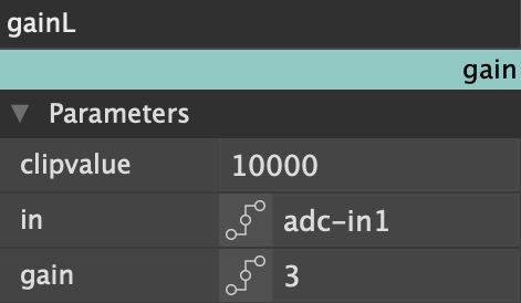
Fig. 6.11 Left channel gain
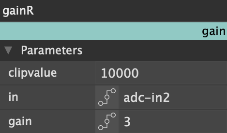
Fig. 6.12 Right channel Gain
Both gain modules have their gain manually set to 3 dB, providing a fixed amount of gain for each channel which cannot be changed by the user.
Upon uploading the algorithm to Emote, no controls will be displayed to the user, but 3 dB of gain will be applied to both channels. This algorithm is not intended to be complex, but to demonstrate in simple terms how audio signals travel within the VSIG patching environment.