6.2.3. VSig Beginner Tutorial #3 - Filters
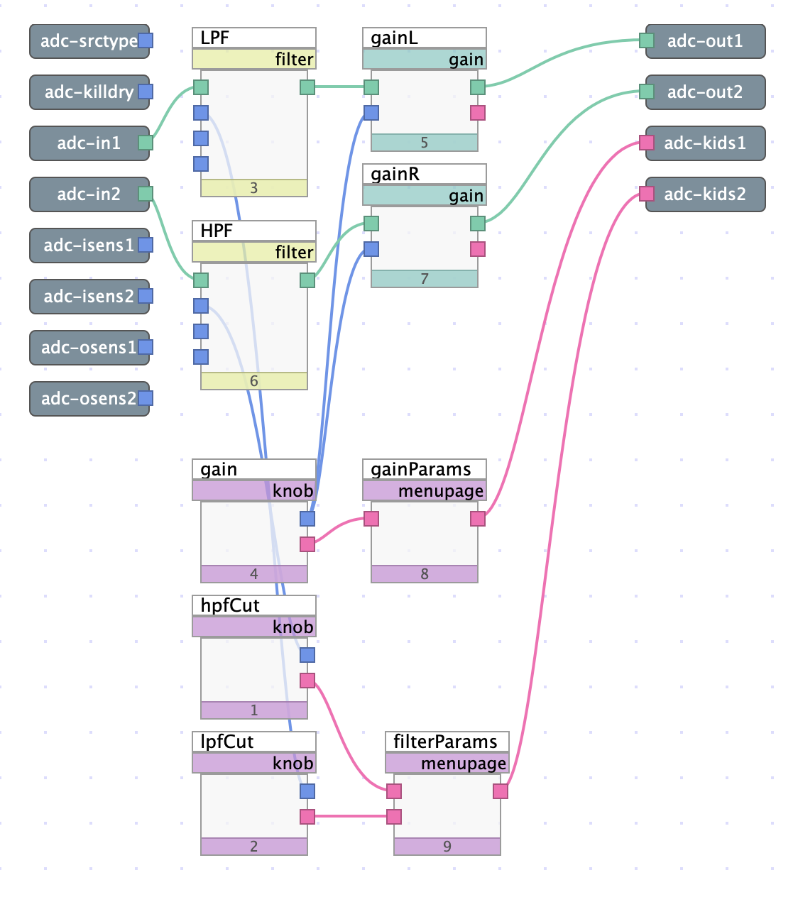
Fig. 6.16 Gain algorithm with filters and interface objects to control cutoff frequency
The above algorithm continues to expand upon the first two tutorials, adding two filter modules and some additional interface objects. Using filters, this patch will demonstrate not only how each input can be processed differently, but also how to create several menupages for a single algorithm.
Download the sigfile here: Simple Gain with Filters.
6.2.3.1. Filters
The signal outputs of adc-1 and adc-2 are routed to the input of two filter modules, titled LPF (Low Pass Filter) and HPF (High Pass Filter) respectively.
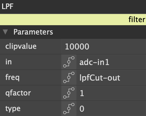
Fig. 6.17 Module editor for Low Pass Filter
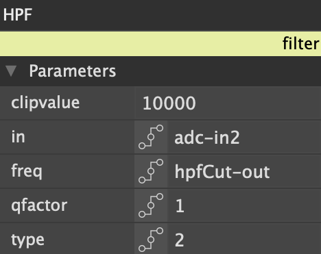
Fig. 6.18 Module editor for High Pass Filter
Looking into the module editor, each filter has a different value for the “type” parameter, which specifies filter type (low pass, band pass, high pass, or notch). “0” specifies a low pass filter, “1” specifies a band pass filter, “2” specifies a high pass filter, and “3” specifies a notch filter. Channel 1 is routed through a low pass filter, whereas channel 2 is routed through a high pass filter.
6.2.3.2. Interface
Each filter has a knob connected to its frequency control input, allowing for individual control over the cutoff frequency of each filter. Although these knobs could’ve been connected to the original menupage module by adding more user inputs, in this case a new menupage was added to create a more organized UI.
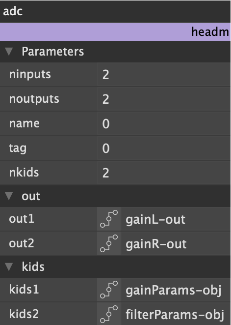
Fig. 6.19 Head module editor, with nkids set to 2
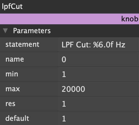
Fig. 6.20 Knob module controlling Low Pass Filter cutoff frequency
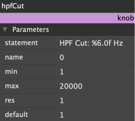
Fig. 6.21 Knob module controlling High Pass Filter cutoff frequency
Each menupage requires its own adc-kids connection. To add more adc-kids, click on any head submodule to open the head module editor, and specify the number of adc-kids in the nkids field (in this case 2).
Upon uploading the algorithm to Emote, two separate menus will be displayed, labeled “Gain” and “Filter.” The Gain menu will have one knob labeled “Gain,” and the Filter menu will have two knobs labeled “LPF Cut” and “HPF Cut.” The low pass filter will only affect the channel 1 input, and the high pass filter will only affect the channel 2 input. The gain knob will affect both channels.