6.2.8. Creative Uses of Bridge Modules
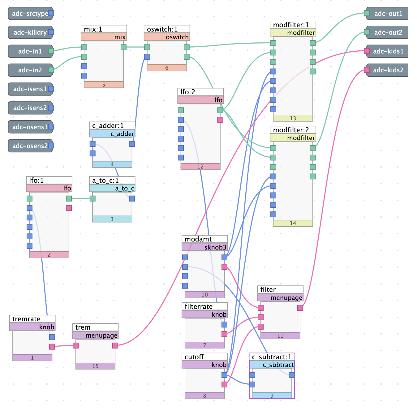
Fig. 6.34 “Stereo Tremolo” esque algorithm using the a_to_c module
The above patch demonstrates how bridge modules, in this case the a_to_c module, can be used for creative effects. In this case, an LFO is used in combination with c_adder and a_to_c to control an oswitch which only outputs to the left or right channel at any given time. The result is a stereo tremolo effect, used in combination with modulated filters for a “phase-y” sound.
The resultant sound of this algorithm includes two distinct effects: a stereo tremolo, which uses an LFO converted to a control signal to constantly switch between outputting to only the left or right channels, and an effect which has elements of a phaser and an autowah, achieved using modfilters. This algorithm is mainly designed to demonstrate one creative usage of the a_to_c bridge module, and how it may be used with other modules to create dynamic, multidimensional effects.
Download the sigfile here: Creative Uses of Bridge Modules.
6.2.8.1. Audio to Control Structure
The a_to_c module takes an audio signal input and converts it to a control signal output. In this case, an LFO is the audio input and is converted to a control signal on output. The converted signal is used to control a switch, which routes a single audio input to one of two outputs depending on the control input.
Before proceeding, let’s dive deeper into how oswitch works. As previously discussed, oswitch switches between a given output based on the input control value. Output 1 is triggered when the control value is less than 1, and output 2 is triggered when the control value is greater than or equal to 1.
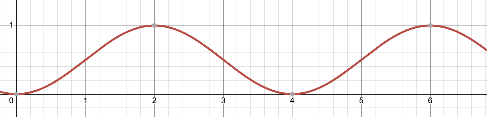
Fig. 6.35 Time domain representation of the LFO output
In this case, the control signal is constantly oscillating. By default, the LFO module (in unipolar mode) outputs in a range between 0 and 1. Clearly this control signal will never cause the oswitch to activate to output 2, as a value of at least 1 is required to do so. As a result, it is necessary to “vertically shift” our LFO signal in order to achieve the desired effect.
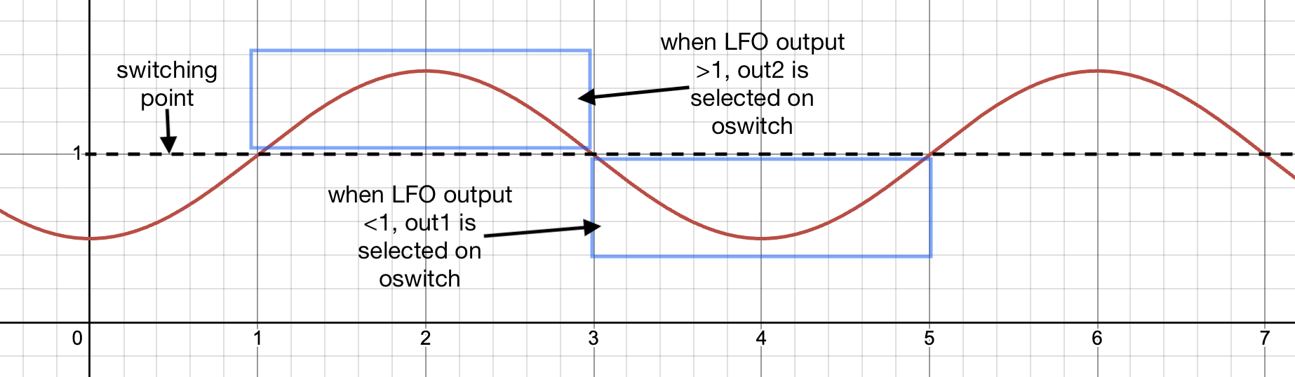
Fig. 6.36 “Vertically shifted” LFO output, using c_adder module
Vertical shifting is achieved using the c_adder module, which allows control signals to be added together. By adding a constant 0.5 to the LFO output, the signal outputs between 0.5 and 1.5. The result is a “ping pong” type effect, where audio constantly and uniformly switches between outputting to only the left or right channel.
6.2.8.2. Modulated Filters
Each switch output is routed to the input of a modfilter module. The cutoff frequency of each module is modulated by another LFO. The user is given control of the cutoff frequency, amount of frequency modulation, and LFO rate.
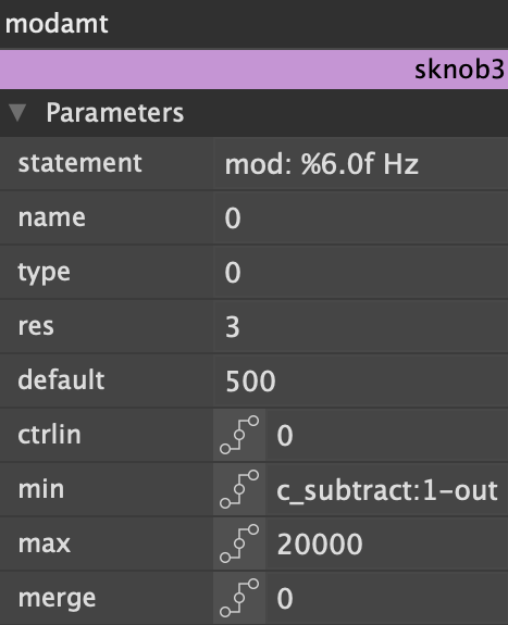
Fig. 6.37 Module editor for sknob3
The sknob3 module, used to control the amount of cutoff frequency modulation input, is used so that the minimum amount of frequency modulation is constantly dependent on the cutoff frequency. For example, with a cutoff frequency of 1000Hz, the user should only be able to modulate the cutoff frequency by as little as –1000Hz. This is achieved by using the control output of the cutoff knob to control the minimum possible value accessible by the modamt knob. The sknob3 module is one of the only interface objects whose minimum and maximum values can be affected by a control signal and is ideal for situations such as these.