6.2.9. Ducking and Sidechain Compression
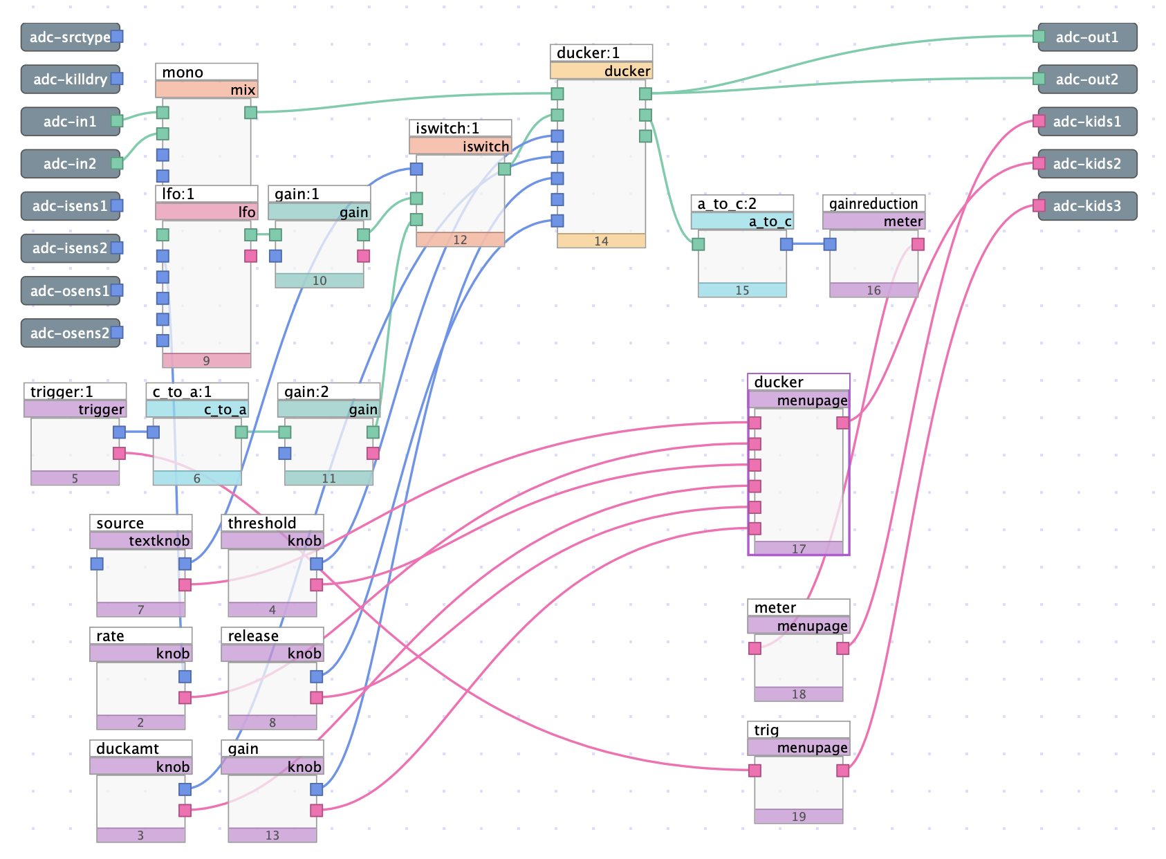
Fig. 6.38 Automatic/manual ducker algorithm
This algorithm explores a creative use of sidechain compression using the ducker module, which acts as a compressor with a sidechain input. By targeting the sidechain input with various audio sources, one may achieve a rhythmic, pulsating ducking, manually triggered ducking, and much more.
This algorithm acts as a ducker which can be set to duck either automatically or manually using the source toggle switch. In automatic mode, ducking occurs periodically at a user definable rate. In manual mode, ducking only occurs at the instant the “trigger” button is clicked. In both modes, the user has control over the threshold, amount of ducking, release time, and overall gain.
Download the sigfile here: Ducking and Sidechain Compression.
6.2.9.1. Sidechain with LFO
By default, this algorithm uses an LFO as its side chain input, specifically a ramp wave.
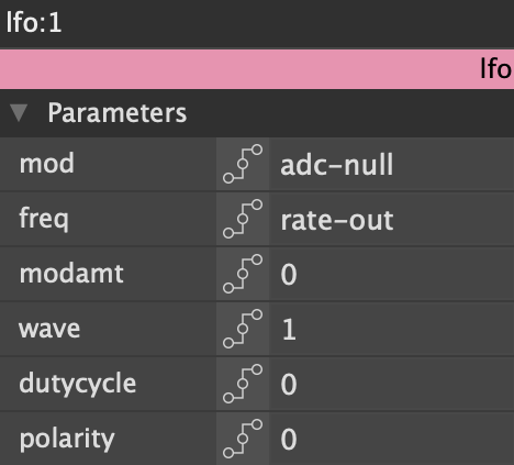
Fig. 6.39 LFO module editor
Looking into the LFO module documentation, you may notice that there is no option for a ramp wave shape. Instead, a triangle wave (indicated by a 1 in the wave field) with 0% duty cycle is used, effectively a negative ramp sawtooth wave.
Using an LFO causes gain reduction to occur periodically but at a uniform rate selectable by the user. A small amount of gain is applied to the LFO to ensure that it exceeds the threshold, although threshold and ratio can also be dialed in by the user to achieve a desired effect.
6.2.9.2. Manual Sidechain with Trigger
This algorithm also includes a source toggle in the form of a textknob. Toggling the switch changes the sidechain source to a trigger, meaning that gain reduction will only occur at the instant the trigger is clicked.
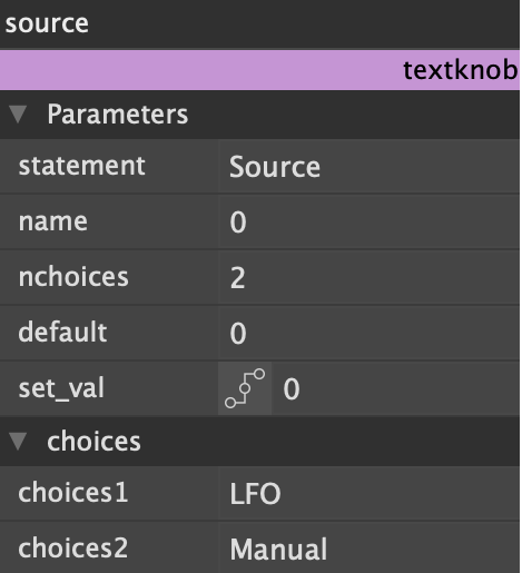
Fig. 6.40 Textknob module editor. Textknobs with only two choices are automatically displayed as a binary switch, as opposed to a drop down menu. Despite both choices being labeled, these labels will not be shown to the user.
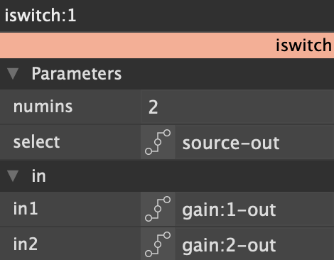
Fig. 6.41 Iswitch module editor. The textknob shown above, labeled “source,” acts as the control input.
Because the trigger module outputs a control signal, a c_to_a bridge must be used so that the signal is accepted by the sidechain input. Gain is once more used to ensure that the trigger output exceeds the ducker threshold.
6.2.9.3. Metering
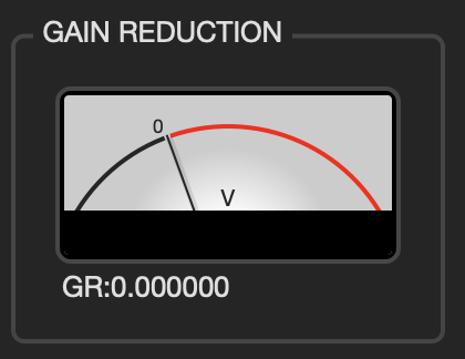
Fig. 6.42 Analog style meter used to show gain reduction
Users can ensure that the ducker is causing gain reduction using the meter module, which displays an analog style meter. An a_to_c bridge is required to display gain using the meter, as the gain output from the ducker is an audio signal.