6.2.6. VSig Beginner Tutorial #6 – Parametric EQ
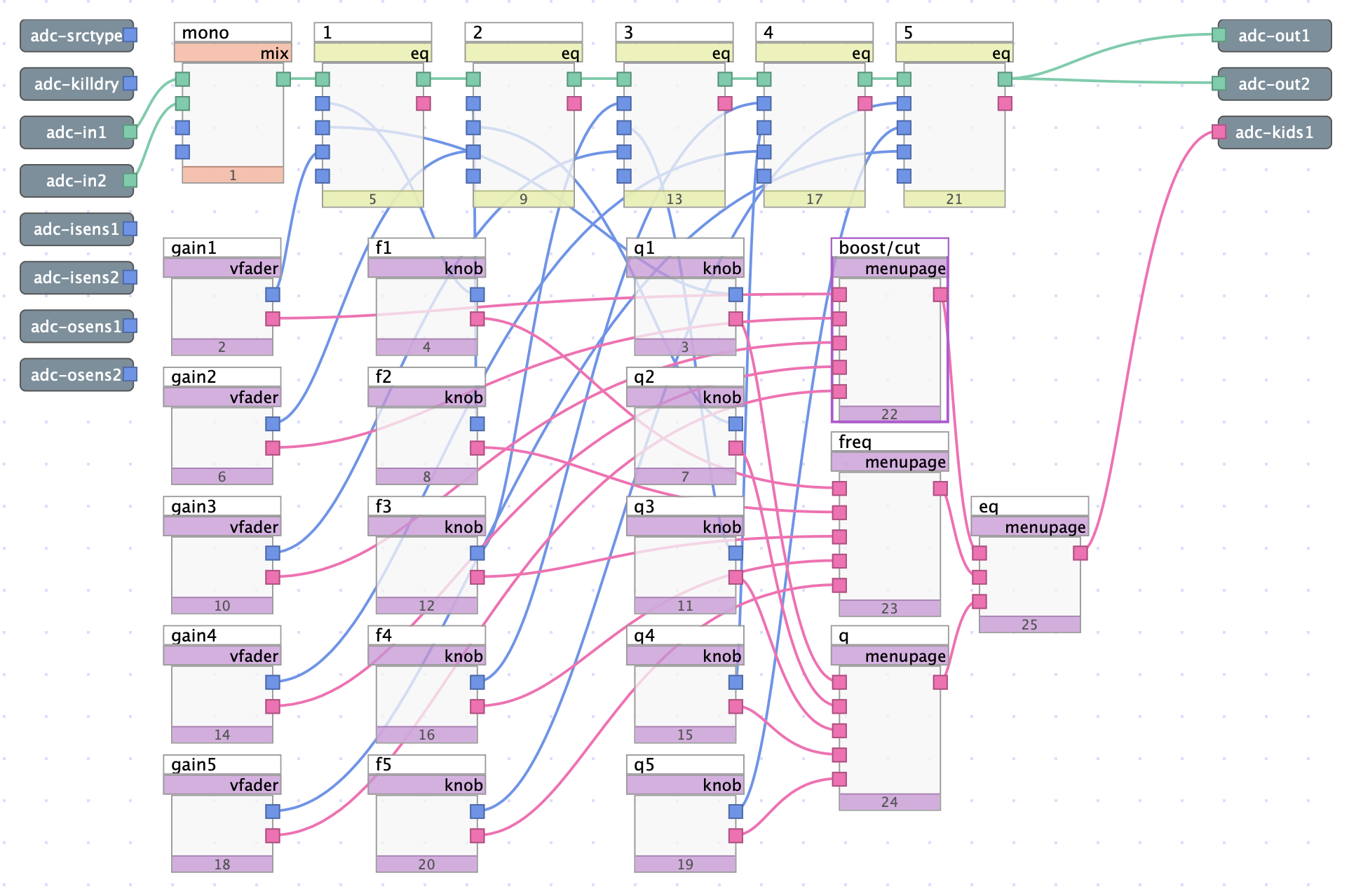
Fig. 6.29 5-band parametric equalizer algorithm
The algorithm above expands upon the previous tutorial, converting a simple graphic equalizer into a parametric equalizer with increased user control over EQ parameters. By just adding interface modules, a simple algorithm can become a much more powerful tool.
Download the sigfiles here: Parametric EQ1 and here Parametric EQ2.
6.2.6.1. EQ Module pt.2
This algorithm utilizes the same construction of five series connected EQ modules, but now almost all parameters are controllable by the user. Parameter control is best demonstrated using the module editor:
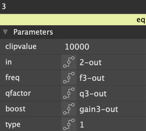
Fig. 6.30 Module editor for EQ module
Interface modules (knobs) now control the center frequency and Q factor of each EQ band in addition to boost/attenuation.
The “type” parameter remains defined by manual entry, so that the EQ is made up of a low and high shelf filter on both ends of the spectrum, with three peak/notch filters in between. For an even more customizable and modular EQ, the user may be given control over the type of each band (perhaps via a textknob).
6.2.6.2. Interface Module pt.2
Vfader continues to be used to control the boost/attenuation of each EQ band, while knobs are used to control both the center frequency and Q factor of each band. All Q factor knobs function identically, while each frequency knob varies in its “min” and “max” parameters.
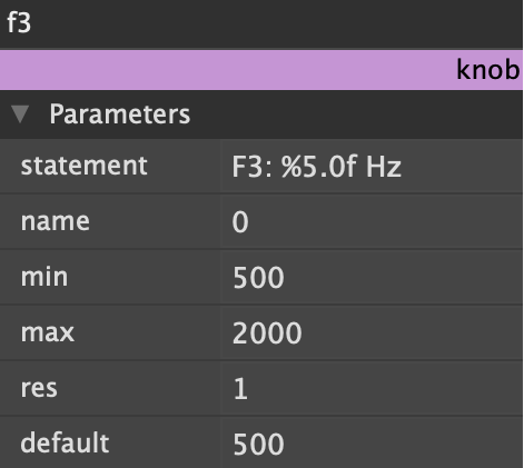
Fig. 6.31 Module editor for knob module, which controls the third EQ band’s frequency
The module editor above shows the parameters of a knob which controls the center frequency of our third EQ module. The knob is limited to values between 500 and 2000 Hz, roughly encompassing the mid frequency range of the audible spectrum. In ascending order, the frequency ranges for each knob are:
20 Hz – 250 Hz
250 Hz – 500 Hz
500 Hz – 2000 Hz
2000 Hz – 4000 Hz
4000 Hz – 20000 Hz
Another solution for defining the frequency range of each knob could be to use sknob3, which accepts a control input for both its maximum and minimum values. Doing so would allow for each knob to have variable frequency range dependent on the output values of the other knobs. Integration of sknob3 for frequency control is left as an exercise for the reader.
6.2.6.3. EQn Series Equalizer
Up to this point, several EQ modules have been used to create our EQ algorithms. This is a perfectly acceptable way of creating a multiband equalizer, but it may be easier (and more organized) to instead use one instance of the EQn module. EQn is composed of up to eight series connected EQs all within a single module. Converting our current algorithm to instead use EQn would look something like this:
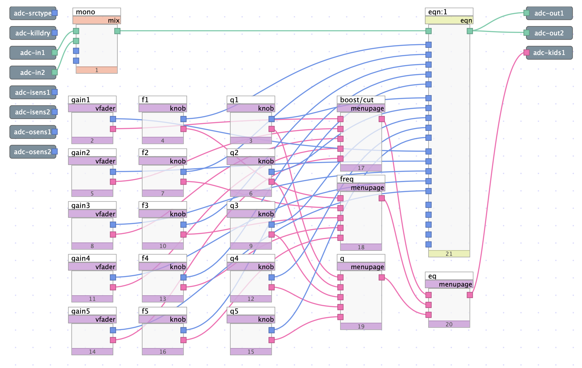
Fig. 6.32 5-band parametric equalizer algorithm, using EQn instead of five EQs
All interface modules are completely unchanged, but now a single EQn module is used in place of 5 EQ modules. The resultant sound and usability are also unchanged, but the algorithm itself is slightly more concise.
Whether you decide to use several EQs or a single instance of EQn, the user will be presented with a set of five faders, and two sets of five knobs. Faders control boost/attenuation, one set of knobs controls the center frequency of each band, while the other set of knobs controls the Q factor for each band. While still quite a simple algorithm, the integration of expansive and intuitive user controls helps create a highly capable sound shaping tool.